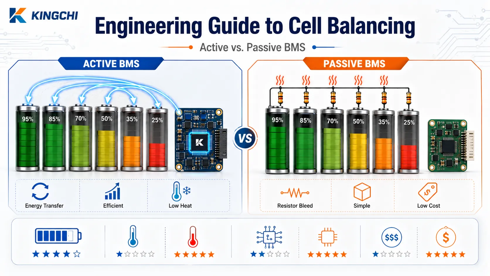
Engineering Guide to Cell Balancing: Active vs. Passive BMS
We see it in the field far too often: a commercial battery pack rated for 6,000 cycles fails well short of its warranty period, not because the cells are dead, but because minor imbalances accumulated cycle after cycle. Cell balancing is the control function that prevents this drift, and its implementation directly determines whether a lithium-ion asset degrades gracefully or spirals into dangerous overvoltage conditions. In procurement conversations, the balancing architecture is rarely a line-item—yet it is the single most consequential circuit-level decision after cell selection.
In this guide, we walk through the root causes of imbalance, the thermal physics behind passive shunting, the topologies that define active redistribution, and the sizing calculations that keep your engineering team from over-specifying a BOM. Our goal is to give you the decision framework and technical depth to evaluate balancing strategies with the same rigor you apply to cell sourcing and pack packaging.
Why Cell Balancing is Critical for Industrial Battery Packs
Cell balancing is a system-level control mechanism in a battery management system (BMS) that equalizes the state of charge (SOC) of individual cells connected in series. Without it, the usable capacity of an entire string collapses to the capacity of its weakest cell, and localized overvoltage during charging becomes a thermal runaway risk.
Mitigating the Weakest Link Problem in Series Strings
In a series configuration, current flows identically through every cell. The moment any single cell hits its upper voltage limit before the others, charging must stop—even if the remaining cells are at 85% SOC. That’s capacity left on the table. On discharge, the pack is similarly limited by the first cell to reach its undervoltage cutoff. The result is a utilization loss far greater than the capacity mismatch of the lowest cell, because the entire string is throttled by a single outlier. Our team has seen 100 Ah packs effectively deliver only 88 Ah due to a 4% SOC spread that went uncorrected for 800 cycles.
Operational Safety and Thermal Runaway Prevention
When imbalance forces the BMS to push a high-SOC cell further into overcharge territory to compensate for a lagging neighbor, the anode potential can dip below the lithium plating threshold. That’s the prelude to dendrite formation and, if left unchecked, an internal short circuit capable of triggering catastrophic thermal runaway. In industrial packs where safety margins are already squeezed to meet energy density targets, the balancing function is not just a capacity optimization feature—it’s a required safety barrier. We advise any procurement team reviewing third-party BMS designs to verify that the balancing logic incorporates both cell-voltage and temperature-fault interlocking, not simply SOC thresholds.
The Root Causes of Cell Imbalance: System-Level Drift
Real cell imbalance is driven by minor variations in self-discharge rate, unequal BMS leakage current across monitoring channels, and uneven temperature distribution across the physical pack. It is not caused by initial capacity mismatches—those limit total pack capacity, but don’t create ongoing SOC divergence if coulombic efficiency is matched.
True Drivers of SOC Drift: Self-Discharge and Leakage Currents
Every cell leaks charge chemically, and every BMS monitoring IC draws a quiescent current from the cells it monitors. While these numbers are tiny—often under 50 µA—they are rarely identical across all cells. Over a 30-day float period, a 5 µA difference between two channels in a monitoring IC can create a 3.6 mAh divergence, which compounds into a measurable SOC gap after a few months. We’ve measured leakage asymmetry of 12 µA in one production BMS board, which, uncorrected, translated to a 1.8% SOC drift over 90 days. That’s enough to start eroding capacity on packs with tight balancing windows.
The Accelerating Effect of Thermal Gradients
A thermal management layout that leaves a temperature differential of just 5°C across a pack module can double the self-discharge rate of the warmer cells relative to the cool ones. The Arrhenius relationship governing side-reaction kinetics means that even small temperature non-uniformities accelerate the drift exponentially over time. In our field data, packs with poor thermal uniformity commonly exhibit 3–5% SOC spread within 500 cycles, while identically built packs with forced-convection cooling maintain under 1% spread. This is why cell balancing cannot be evaluated in isolation from the thermal design—it is both a cause and a victim of thermal gradients.

Passive Cell Balancing: Mechanisms and Thermal Engineering Challenges
Passive cell balancing uses a switched shunt resistor circuit to dissipate excess energy from high-SOC cells as heat, preventing overcharge while weaker cells finish their cycle. It is the lowest-cost approach and remains standard in most low-to-mid-rate industrial packs, but it places a direct thermal burden on the enclosure.
Switched Shunt Resistor Architectures
The typical topology places a MOSFET in series with a power resistor across each cell. When the BMS monitoring IC detects a cell voltage above the balancing threshold (usually during the constant-voltage charging phase), it turns on the FET, bleeding current through the resistor until the cell matches the pack average. This is a straightforward dissipative control, but it requires careful coordination: if the BMS enables balancing on many cells simultaneously, the collective heat dump can overwhelm passive cooling. We prefer implementations that stagger shunting across adjacent channels to localize heat dissipation.
Calculating Heat Dissipation Limits
The heat generated per cell is P = Vcell × Ibalance. For a 1 A balancing current on a 4.2 V lithium-ion cell, that’s 4.2 W of thermal power per channel. Multiply by 10 cells in a module balancing concurrently, and you have 42 W of localized heat that must be rejected without raising the internal pack temperature beyond safe limits. The table below gives a practical sense of the thermal load at common balancing currents.
| Balancing Current (mA) | Heat per Cell at 4.2V (W) | Heat for 8 Concurrent Channels (W) | Thermal Management Concern |
|---|---|---|---|
| 50 | 0.21 | 1.68 | Negligible in most enclosures |
| 150 | 0.63 | 5.04 | Requires airflow or metallic heat-spreader |
| 500 | 2.10 | 16.8 | Active cooling or derating may be mandatory |
| 1000 | 4.20 | 33.6 | Design limits of most passive-cooled packs |
Note: Heat dissipation values assume simultaneous balancing on all channels; actual thermal loading depends on the BMS staggering algorithm. Buyers should request thermal images of the BMS board under maximum balancing load during supplier evaluation.
Active Cell Balancing: Topologies for Energy Redistribution
Active cell balancing uses capacitive, inductive, or DC-DC converter topologies to shuttle charge from higher-voltage cells to lower-voltage cells with minimal thermal loss. This non-dissipative approach becomes attractive when balancing windows are short or thermal headroom is scarce.
Capacitive Shunting: Switched-Capacitor Systems
A switched-capacitor array connects a flying capacitor alternately across adjacent cells. Charge transfers from the higher-voltage cell to the capacitor, then from the capacitor to the lower-voltage neighbor, with no active microcontroller direction needed. The simplicity of this scheme is appealing, but the balancing speed decays across long series strings because charge must propagate cell-by-cell. In a 16S pack, correcting a SOC mismatch at the far ends can take tens of hours, making this topology best suited for small-format packs under 8S.
Inductive and Transformer-Based Topologies
When balancing speed matters, bidirectional flyback transformer designs shine. A single transformer with multiple secondary windings can move energy from the entire pack to a targeted cell, or vice versa, all controlled by a digital BMS IC. This approach supports balancing currents of 1–5 A with efficiency above 85%, and because energy is recycled rather than burned, thermal load is drastically reduced. However, the custom magnetics and the required high-voltage isolation push BOM cost significantly above a passive shunt array.
Bidirectional Buck-Boost Converters
For heavy-duty industrial applications—think 200 Ah+ packs in continuous-duty AGV or material handling—bidirectional buck-boost balancers offer the highest energy transfer rates. These act as local DC-DC converters between adjacent cell groups, allowing balancing currents of 5–10 A. They also provide a secondary benefit: because each converter operates independently, they can maintain balance even during discharge, something passive and simple active topologies cannot do. The trade-off is complexity; each balancer channel is a full switching regulator, driving up cost and PCB real estate.
Algorithmic Implementations: When and How to Balance
Algorithmic execution of cell balancing is typically divided between simple voltage-based balancing and complex SOC estimation models, executed primarily during the top-of-charge phase.
Voltage-Based Balancing vs. State-of-Charge (SOC) Estimation
Voltage-based methods compare cell terminal voltages and enable balancing when a cell exceeds a fixed threshold. While inexpensive and easy to implement, terminal voltage is a poor proxy for SOC when charge or discharge currents are flowing, due to cell internal resistance drops. A cell under a 0.5C load can read 80 mV higher than its true OCV, causing premature balancing activation. SOC estimation algorithms, often using Kalman filters or coulomb counting with periodic OCV recalculations, offer far more accurate triggering but require validated cell models. We recommend voltage-based thresholds only for applications with long, uninterrupted float-charge periods; for dynamic load profiles, SOC-based balancing avoids unnecessary shunting and associated thermal cycling.
Top-Balancing vs. Bottom-Balancing Strategies
Top balancing equalizes cell voltages at the end of the charge cycle, ensuring that no cell exceeds its maximum voltage. This is the default for EV and stationary storage, where maximizing capacity at full charge is the goal. Bottom balancing, in contrast, aligns cells at the discharge cutoff, which ensures that maximum usable capacity can be extracted at the end of discharge. This strategy is favored in defense applications or material handling equipment where the pack must deliver full rated energy right up to the undervoltage limit. The decision is not purely academic: misapplying a top-balance strategy on a bottom-balanced pack can lead to deep-discharge of weaker cells and irreversible capacity loss.
Sizing Your Balancing System: Speed and Current Calculations
Sizing a balancing system requires calculating the minimum current needed to offset worst-case cell self-discharge rate variation and leakage current differences within the available charging idle window.
Estimating Necessary Balancing Currents
Suppose a 100 Ah pack has a measured cell-to-cell self-discharge variance of 2% per month. That’s 2 Ah per month, or roughly 2.7 mA average drift current. Add a worst-case BMS leakage imbalance of 50 µA, and the balancing system must be able to correct about 3 mA continuously just to hold the pack neutral. But in practice, balancing only operates during the final 30-minute constant-voltage window of a charge cycle, so the balancing current must be sized to correct several days’ worth of drift within that window. A 150 mA passive balancer can correct about 75 mAh per half-hour, which covers roughly 25 hours of drift. For faster correction, active balancing at 1–2 A shrinks that time to minutes. The math drives home why passive balancing is rarely pushed past 150 mA in sealed enclosures—the heat quickly becomes unmanageable.
The Impact of Cycle Profiles on Balancing Windows
In applications where the pack sees frequent partial charges—such as opportunity charging in warehouse AGVs—the balancing window shrinks to only a few minutes. This forces the engineer to either increase balancing current (and accept the thermal penalty) or accept a slow SOC drift. One strategy we’ve deployed for a specialized battery pack used in high-throughput automated guided vehicles was to over-spec the active balancing current to 2 A per cell, enabling full correction during the 15-minute top-up breaks between shifts without any additional heat rise. Without that active path, the pack would have required an extra 80 minutes of idle time per day just for balancing.
Decision Matrix: Active vs. Passive Balancing for B2B Deployments
Choosing between active and passive cell balancing depends on pack capacity, continuous duty-cycle demands, thermal boundaries, and total system cost constraints. There is no universal “better” solution—only a better fit for the operational profile.
Total Cost of Ownership (TCO) and Lifecycle Analysis
Active balancing adds upfront BOM cost—often $15–$40 per channel for transformer-based or buck-boost designs—but it can extend pack life by 15–20% in deep-cycling applications by preventing chronic overvoltage stress on marginal cells. For a 500 kWh stationary storage asset, that longevity gain can offset the initial electronics premium within the first 3 years. Conversely, a telecommunication backup battery that floats at 54V for 99% of its life sees miniscule SOC drift; the additional cost of active balancing provides negligible return. The table below summarizes the key trade-offs.
| Balancing Method | Typical Balancing Current | Efficiency | Heat Generation | Best-Fit Application |
|---|---|---|---|---|
| Passive (Shunt Resistor) | 20–150 mA | 0% (dissipative) | High, proportional to current | Float service, low-utilization backup packs, lithium battery packs with generous idle time |
| Active (Switched Capacitor) | 100–500 mA | 80–95% | Low | Small-format packs (4S–8S), UAV batteries, handheld equipment |
| Active (Transformer/Flyback) | 1–5 A | 85–93% | Very low | Industrial packs with short balancing windows, high discharge rate batteries |
| Active (Bidirectional Buck-Boost) | 5–10 A | 90–96% | Lowest thermal load | Heavy-duty AGVs, continuous cycling ESS, AGV battery packs |
Note: Efficiency figures are typical for well-designed circuits; actual values depend on component selection and operating conditions. Buyers should request efficiency curves from the BMS supplier at the expected balancing current range.
B2B Sourcing and Supplier Qualification Checklist
When evaluating a balancing system for procurement, go beyond the topology name. Verify these parameters directly with the BMS supplier:
- Thermal dissipation margins: Can the board handle all channels balancing simultaneously at the rated current without exceeding component temperature ratings?
- Peak balancing current: Is the stated current a true continuous rating or a peak transient? Request the derating curve.
- BMS standby power draw: What is the quiescent current per monitoring channel, and how does it vary across temperature?
- Safety standard compliance: Look for UL 1973 or IEC 62619 documentation for the final assembly, and verify that the balancing circuit includes independent overvoltage cutoffs, not relying solely on the balancing algorithm.
- Cell chemistry compatibility: Confirm that the balancing algorithm’s voltage thresholds and timing are optimized for your cell’s OCV curve, especially if using LFP chemistry.
- Production BMS IC selection: Request the BMS IC datasheet and cross-check the guaranteed minimum balancing current and channel-to-channel leakage matching specifications.
Partnering with a BMS Engineering Expert for Custom Pack Development
Deploying a reliable cell balancing strategy requires matching BMS hardware specifications with your specific cell chemistry and cycle profile. This is not a one-size-fits-all selection—balancing current, thermal design, and algorithm must be tuned to the pack’s physical layout and charge/discharge profile.
We recommend engaging a custom battery pack manufacturer that can simulate pack thermal profiles under both passive and active balancing scenarios before any tooling commitment. A proper pre-production simulation will model the worst-case thermal gradient and the accumulated SOC drift over the projected service life, allowing the balancing architecture to be right-sized rather than over-engineered. When you approach a potential supplier, have these specifications ready: nominal pack capacity and series/parallel (S/P) configuration, expected ambient temperature range and cooling method, typical charge/discharge cycle frequency and duration, allowable idle float time, and target cost-per-kWh boundaries. This allows the integrator to immediately narrow the topology options and provide an accurate BOM estimate.
Whether you are sourcing a standalone battery management system for an in-house pack or evaluating a complete battery pack with integrated balancing, the engineering conversations should focus on balancing performance under real field thermal conditions, not just bench-top specifications. Our team regularly supports these evaluations for custom battery solutions across industrial, defense, and stationary storage sectors.
Frequently Asked Questions
Can cell balancing fix a permanently damaged or worn-out cell?
No. Cell balancing cannot restore lost chemical capacity in an aged or physically damaged cell; it only maximizes the usable capacity of the remaining functional cells in the series string. Once a cell has lost significant capacity due to degradation, replacement is the only corrective action.
Why is cell balancing typically restricted to the charging phase?
Voltage measurements are most stable and representative of actual SOC during the end of the charging phase (top-charging), whereas dynamic loads during discharge introduce internal resistance voltage drops (I × R drops) that distort terminal voltage readings. Balancing during discharge would require highly accurate SOC estimators and can compromise energy delivery if not carefully controlled.
What are the risks of using high-current active balancers in small packs?
High balancing currents in low-capacity cells can lead to local voltage overshoots, rapid SOC oscillation between channels, and unnecessary thermal stress on adjacent components. For small packs under 10 Ah, keeping balancing current below 200 mA usually avoids these issues.
How does cell chemistry (e.g., LFP vs. NMC) affect cell balancing?
Lithium Iron Phosphate (LFP) has an extremely flat open-circuit voltage curve, making voltage-based balancing difficult except at the very top of the charge cycle, while Nickel Manganese Cobalt (NMC) has a steeper curve that facilitates easier voltage-based estimation. This is why LFP packs often require SOC-based balancing algorithms or very tight voltage thresholds to avoid false triggers.
Is active cell balancing worth the extra cost for stationary energy storage systems (ESS)?
For systems with brief charging windows and constant daily cycling, active balancing can reduce degradation and thermal loads enough to justify the upfront electronics cost. For standard backup power applications with long float periods, high-quality passive balancing at 50–100 mA is typically more cost-effective and thermally manageable.
Frequently Asked Questions
Get a Fast, Custom Power Quote