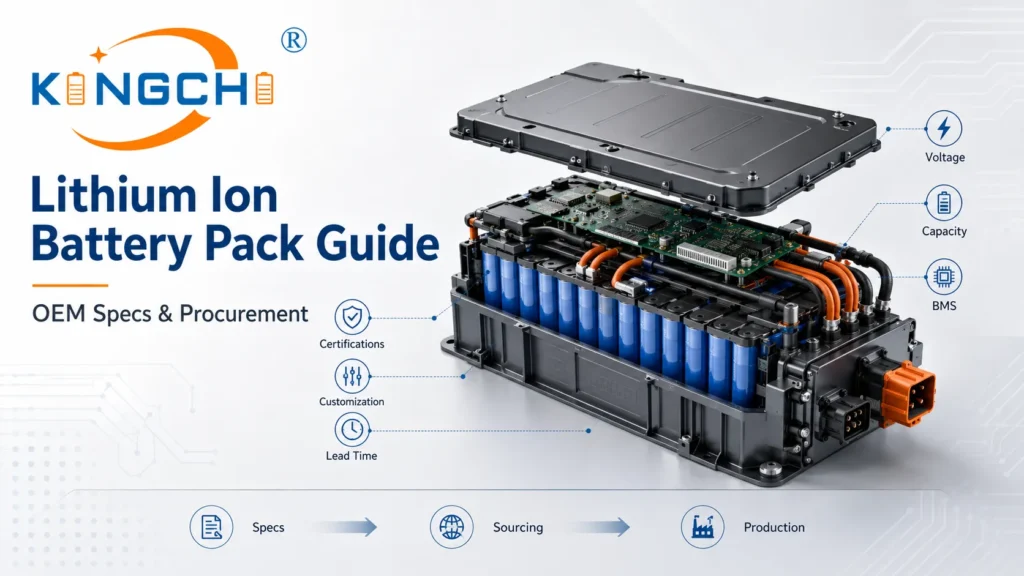
Custom OEM Battery Manufacturing & Design: Technical Guide
When a medical ventilator loses power mid-surgery or a defense drone drops out of the sky because of a battery failure, the root cause is rarely a single bad cell. It’s a design or procurement decision made 18 months earlier. Selecting a partner for custom OEM battery manufacturing is the single most consequential engineering and sourcing choice a hardware team will make—yet it’s often treated as an afterthought. In this guide, we’ll walk through exactly what defines an OEM battery system, where the real engineering risks hide, and how to evaluate suppliers so your pack survives field conditions, not just the lab.
Demystifying OEM Battery Manufacturing: Definitions, Sourcing Formats, and ODM Differences
Decision rule: OEM battery manufacturing means the supplier engineers a battery pack to your unique specifications—mechanical, electrical, and thermal—with full design ownership resting with your team. This contrasts sharply with ODM (Original Design Manufacturer) models where you adapt a supplier’s pre-existing design.
Defining OEM Battery Engineering in B2B Contexts
In regulated industries such as medical devices, defense, industrial automation, robotics, and electric vehicles, off-the-shelf batteries rarely meet the mechanical integration, safety, and telemetry demands of the final product. OEM battery pack design begins with a set of proprietary requirements: the enclosure geometry, the continuous and peak discharge profiles, the environmental temperature envelope, and the communication interface between the pack and the host system. The manufacturer then designs the cell array, welds, insulation, housing, and Battery Management System (BMS) around those inputs.
This is fundamentally different from buying a catalog pack and reshaping your device to fit it. When we engage in an OEM project, every cell, wire route, and protection threshold is specified against a shared requirement document. The result is a system where the pack is a structural and functional extension of the device, not a generic add-on. We’ve seen engineering teams cut six months of field rework and qualification time simply by front-loading that design discipline.
The Engineering Trade-offs: OEM vs. ODM Battery Architectures
The core difference is intellectual property and design ownership. Choose OEM when your hardware requires a custom-molded enclosure, highly specific current draws, or custom BMS telemetry. Choose ODM when you want to minimize upfront NRE costs and can adapt your product casing to a pre-existing battery design. Designing custom battery packs under an OEM agreement gives you full control over cell grade, safety margins, and lifecycle management, but it demands a longer development timeline and greater engineering investment from both sides.
ODM suppliers offer pre-engineered form factors—often 18650 or 21700-based plastic sleds—that can be rebranded or lightly modified. The BMS is usually a standard protection circuit with limited communication options. That model works for consumer electronics or low-criticality industrial tools. However, when a device cannot tolerate a 1.5-second voltage sag during a motor start-up, or must report state-of-health telemetry across a CAN bus every 100 ms, the ODM path quickly becomes a constraint. We find that most B2B buyers end up requiring OEM vs ODM batteries evaluation early because the performance gaps become visible during DFMEA reviews.
The Development Lifecycle: What to Expect from Kickoff to Volume Run
A typical OEM battery development project spans 9 to 18 months. The timeline isn’t driven by slow manufacturing; it’s governed by the physics of cell cycling, firmware development for the BMS, and multi-region safety certification testing. The following phases give engineering leads a realistic planning framework:
- Phase 1 — Specification & Feasibility (Months 1–2): Joint definition of electrical, mechanical, and safety requirements. Concept schematic and cell selection modeling.
- Phase 2 — Prototyping & Design Validation (Months 3–7): 3D printed enclosures, hand-built packs, initial BMS firmware, and iterative cell cycling tests to validate capacity fade.
- Phase 3 — DFM & Pilot Tooling (Months 8–12): Design for manufacturing reviews, steel tooling for plastic enclosures, automated assembly line setup, and first pilot run.
- Phase 4 — Certification & Product Launch (Months 12–18): UN 38.3 transport testing, UL 2054 pack safety evaluation, and customer acceptance testing before scaling to volume.
Missing a milestone in Phase 3 often cascades into a five-month delay because tooling corrections and recertification cycles have hard lead times. We advise customers to treat the pilot tooling review as the project’s true gate.
Sourcing OEM Battery Manufacturing: Core Cell Chemistries and Engineering Specifications
Selecting the right cell chemistry and packaging format dictates the system’s energy density, thermal threshold, safety certifications, and total cycle life. Without a deliberate match, even the best BMS cannot salvage performance gaps or thermal instability.
Primary vs. Secondary Chemistry Selection Matrix
The table below maps the four most common lithium-ion chemistries used in industrial OEM packs to their application sweet spots and procurement risks. We recommend that sourcing teams use this as a first-pass filter before engaging suppliers.
| Chemistry | Voltage Range (Nominal) | Energy Density (Wh/kg) | Typical Cycle Life | Best-Fit Application | Procurement Concern |
|---|---|---|---|---|---|
| LFP (Lithium Iron Phosphate) | 3.2 V | 90–120 | 2,000–4,000+ | Medical carts, AGVs, stationary energy storage | Lower energy density may require larger packs |
| NMC (Nickel Manganese Cobalt) | 3.6–3.7 V | 150–220 | 800–1,500 | Robotics, drones, defense portables | More prone to thermal runaway; needs robust thermal management |
| NCA (Nickel Cobalt Aluminium) | 3.6 V | 200–260 | 500–1,000 | High-performance EVs, aerospace | High raw material cost; limited second-source options |
| LCO (Lithium Cobalt Oxide) | 3.6–3.7 V | 150–200 | 500–1,000 | Consumer devices, low-cycle industrial | Poor thermal stability; not recommended for critical systems |
Note: Cycle life values are based on 80% depth of discharge at 25°C ambient. Buyers should verify test conditions with each cell supplier.
For applications with heavy surge loads—like an electric valve actuator in subsea oil & gas—custom lithium-ion battery manufacturing often pushes NMC or LFP chemistry toward active cooling integration. In our projects, we often pair LFP with conservative discharge current limits to extend calendar life beyond 10 years, which becomes a major TCO lever.
Cylindrical, Prismatic, and Pouch Form Factor Applications
Form factor drives both mechanical packaging efficiency and thermal management strategy. 18650 cell OEM manufacturing and 21700 cell OEM production excel in high-vibration environments because the steel canister acts as a structural shield and pressure relief path. Cylindrical cells also benefit from the most mature automated assembly lines, which lowers per-pack manufacturing variance. Prismatic cells offer higher volumetric density and easier heat sinking but are more susceptible to swelling if overcharged. Pouch cells deliver the thinnest packaging, but their flexible foil pouch demands strict compression fixtures to prevent delamination and internal short circuits.
Engineering takeaway: If your device must survive mechanical shock above 50G, cylindrical cells with laser-welded nickel strips outperform prismatic alternatives. We default to 21700s when the energy demand exceeds 250 Wh per pack and the enclosure can accommodate a 21 mm diameter cell because they reduce total cell count, thereby lowering assembly complexity and potential tab weld failures.
Cell Matching: The Key to Lifespan and Safety
Cell matching and voltage balancing is the most overlooked step in pack reliability. When cells are placed in series without tight matching of internal resistance (IR) and capacity, the weakest cell limits pack performance and becomes a thermal hotspot. Our internal standard requires that every incoming cell batch is sorted so that voltage variances within a pack do not exceed 10 mV at 50% state of charge, and IR variances are held below 2 mΩ. Cells outside that window are rejected or re-sorted.
- Perform initial open-circuit voltage (OCV) sorting to ±5 mV bins.
- Load the cells into automated impedance spectroscopy testers and group cells with IR within 1.5 mΩ.
- Cycle a small sample from each batch at 0.5C/0.5C for 10 cycles to verify capacity consistency; discard any group with capacity spread > 2%.
- Apply matched groups to series strings and confirm that self-discharge rates remain below 2% per month before pack assembly.
This process extends the pack’s useful life by 20–30% compared to random assembly, and it dramatically reduces the likelihood of BMS-triggered shutdowns due to premature cell imbalance.
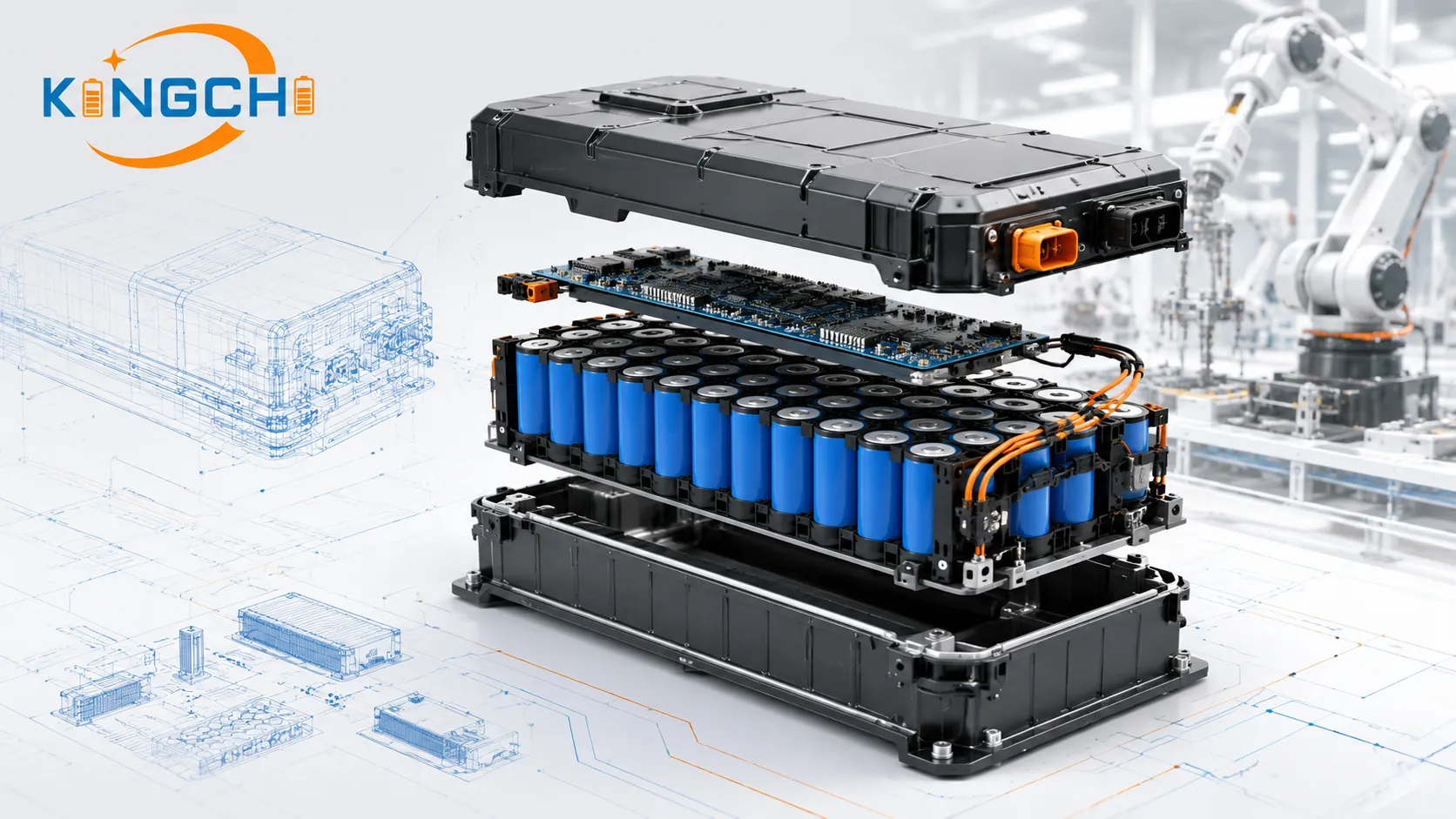
The Core of Pack Safety: Battery Management System (BMS) Architecture
An OEM battery pack is only as reliable as its battery management system, which acts as the primary safety, monitoring, and communication engine of the assembly. The BMS must operate in real time, with hardware-level protection paths that remain functional even if the firmware locks up.
The three non-negotiable safety rules of custom pack engineering are:
- Redundant hardware-level cell isolation: MOSFET or relay disconnect must be triggered by an independent comparator, not solely by the microcontroller.
- Active BMS monitoring of individual cell groups: each series element must be scanned for overvoltage, undervoltage, and overtemperature at least every 100 ms.
- Physical cell spacing engineered for thermal propagation containment: pack layout must prevent one cell in thermal runaway from raising the adjacent cell’s temperature above 80°C, the critical threshold for cascade failure.
Passive vs. Active Cell Balancing Systems
Passive balancing shunts excess charge through a resistor network as heat, typically at currents under 100 mA. It’s simple and inexpensive but cannot compensate for large capacity mismatches that develop over hundreds of cycles. Active balancing moves charge from higher-voltage cells to lower-voltage cells via capacitive or inductive switching, achieving balance in a fraction of the time and without significant thermal loss. For industrial packs with 8S or greater series configurations and a design life of over 1,000 cycles, we strongly recommend active balancing.
Telemetry and Communication Protocols (SMBus, I2C, CAN bus)
The BMS is also the communication hub. For robotics and EV subsystems, a CAN bus interface with BMS integration in OEM batteries allows the host controller to read state-of-charge (SoC), state-of-health (SoH), and cell-level temperature data at sub-second intervals. I2C and SMBus protocols suffice for lower-speed medical devices where the pack reports status every few seconds. The protocol choice determines not just data richness but also the electrical isolation architecture; CAN transceivers typically provide galvanic isolation that protects the host device from pack-ground noise.
Overcurrent, Overvoltage, and Thermal Protection Limits
A well-engineered BMS implements a protection ladder. The primary overcurrent cutoff should trip in under 1 ms at 2× the rated continuous discharge current, while the secondary thermal cutoff should open the charge FETs if any cell thermistor reads above 60°C. We design BMS firmware so that overvoltage thresholds for NMC cells are set at 4.25 V ± 25 mV, well before the 4.35 V electrolyte decomposition region. This margin preserves cell integrity after repeated charge cycles.
Critical Certification and Global Compliance Standards
Hardware manufacturers must verify that their OEM battery partner provides complete trace documentation and third-party laboratory safety testing before shipping any products. No amount of internal validation replaces an accredited report from a recognized lab.
UN 38.3 Safe Transport Testing Requirements
UN38.3 certification for OEM batteries is mandatory for any lithium-based pack shipped by air, sea, or ground. The eight tests—altitude simulation, thermal cycling, vibration, mechanical shock, external short circuit, impact/crush, overcharge, and forced discharge—must be performed on representative samples and documented by an approved testing agency. Buyers should request the full test report, not just a summary certificate, and verify that the test samples match the production configuration in cell type, enclosure, and BMS settings.
Functional Safety Standards: UL 2054, IEC 62133, and CE Marks
UL 2054 evaluates the safety of the finished battery pack, including short circuit, abnormal charging, and fire exposure tests. IEC 62133 focuses on the sealed cells inside portable applications and is the gateway standard for CE marking in the EU. For medical devices, IEC 60601-1 takes precedence, and the battery becomes a critical component requiring additional isolation and fault tolerance validation. We advise customers to define the target geographic markets before the prototype phase so that the required standards can be built into the BMS trip thresholds and mechanical design from day one. Quality assurance in battery manufacturing relies on these external benchmarks to validate safety claims.
Traceability and Environmental Directives (RoHS and REACH Compliance)
RoHS (Restriction of Hazardous Substances) and REACH (Registration, Evaluation, Authorisation of Chemicals) compliance isn’t optional for products sold in the EU. A complete declaration requires a serialized bill of materials with full material composition data. We provide a digital batch record for each pack that ties the BMS serial number to the specific cell lot, BOM revision, and solder paste batch, enabling a rapid recall if a field safety issue is identified.
Custom Battery Pack Manufacturing: From Prototype to Automated Scaling
Moving from custom battery prototyping to high-volume assembly requires structural design-for-manufacturing (DFM) reviews to optimize weld integrity and thermal airflow. The transition point is where many projects stall if the initial design isn’t production-aware.
Design for Manufacturing (DFM) and Thermal Propagation Safety
DFM analysis evaluates whether the cell holder geometry can be injection-molded with consistent wall thickness, whether weld tabs provide enough clearance for automated spot-welding electrodes, and whether the thermal pathway from cell to ambient meets the required Delta-T. A custom battery pack manufacturing run that skips DFM often discovers that a plastic boss snaps during ultrasonic welding or that a cell pocket is 0.3 mm too narrow, causing the automated inserter to jam. We incorporate thermal propagation barriers as early as the DFM stage: flame-retardant mica sheets between parallel groups and vent paths that direct hot gases away from adjacent cells.
Automation vs. Manual Spot-Welding in Cell Assembly
Manual spot-welding is acceptable for prototypes and low-volume builds up to 200 packs per month. Beyond that, automated welding reduces inter-cell resistance variability from ±15% to under ±3%, which directly impacts pack cycle life. Automated cell-sorting and gluing lines also eliminate the risk of a technician inadvertently installing a cell with a 15% lower capacity into a 12S string—the exact type of human error that a $200 BMS can’t fully mitigate.
End-of-Line (EOL) Testing and Diagnostic Protocols
Every pack leaving the manufacturing line must undergo a standardized EOL test regiment. We recommend the following minimum suite:
- Static open-circuit voltage (OCV) and isolation resistance: Confirm pack voltage within 0.5% of nominal and >10 MΩ isolation between power terminals and chassis.
- High-potential (hipot) test: Apply 500 V DC for 1 second (or per applicable standard) to verify no breakdown between live parts and accessible enclosure.
- Dynamic charge/discharge cycle: Run a 0.5C charge to full and a 1C discharge to cutoff while monitoring individual cell voltages for deviations >50 mV.
- BMS verification: Inject a fault condition (e.g., overvoltage on a cell group) and confirm that the BMS opens the protection FETs within the specified response time.
- Accredited third-party UN 38.3 and UL 2054 test reports (not self-declarations).
- Automated cell-sorting equipment with documented voltage-matching tolerance of ≤10 mV and IR tolerance ≤2 mΩ.
- Closed-loop thermal chamber aging on 100% of production packs for at least 24 hours.
- Serialized traceability linking each pack to its BMS firmware revision and cell lot.
- Supplier-managed obsolescence notification procedure for cell chemistries and IC components.
- In-house BMS firmware engineering capability, not dependent on third-party turnkey designers.
Total Cost of Ownership (TCO) vs. Initial Unit Sourcing Costs
While custom OEM packs demand higher upfront investments, they yield a lower battery lifecycle cost (TCO) by reducing field failure rates, warranty claims, and system downtime. The math becomes compelling once you model a 5-year fleet cost.
Non-Recurring Engineering (NRE) Costs and Tooling Investments
Typical NRE fees for an OEM battery project include battery pack design for OEM engineering time, custom BMS PCB layout and firmware development, plastic enclosure mold tooling (often $15,000–$40,000 per mold set), and safety certification testing charges (UN 38.3 plus UL 2054 can exceed $20,000 per design). These costs are amortized over the production volume, so a 20,000-unit program might add only $3–$5 per pack. Buyers should request a detailed NRE breakdown that separates one-time tooling from re-engineering charges for future design changes.
How Cycle Life and Field Defect Rates Impact Lifetime TCO
An aftermarket battery with a field failure rate of 2% per year over 5 years can generate more than $500,000 in service and replacement costs for a 10,000-unit fleet, far exceeding the per-unit price difference. A properly matched OEM pack with 2% capacity matched cells and active balancing typically demonstrates a field defect rate below 0.2% annually and retains 80% of its original capacity after 1,200 cycles, effectively halving replacement frequency.
Decision rule: If a device operates in critical environments (e.g., medical ventilators, subsea oil/gas actuators), standard aftermarket batteries are statistically more expensive over 3–5 years due to unpredictable field failure rates. The OEM path becomes the financially sound choice when uptime requirements exceed 99.5%.
Warranty Protection and Supplier Liabilities
A credible OEM battery manufacturer will provide a warranty that covers both workmanship defects and cell capacity retention, typically for 18–24 months or 500 charge cycles, whichever comes first. Buyers should verify that the warranty explicitly addresses latent cell defects and not just assembly workmanship. We also recommend negotiating a recall liability clause in the supply agreement that defines the cost-sharing framework if a serial defect is discovered post-deployment.
Procurement and Qualification Matrix: Evaluating an OEM Battery Sourcing Partner
Buyers must qualify battery manufacturers based on their process validation controls, supply-chain agreements with Tier-1 cell brands, and formal quality system certifications. The following sections and checklist will aid in structured supplier evaluation.
Quality Management Audits: ISO 9001 vs. ISO 13485
ISO 9001 certification confirms a baseline quality management system, but for medical device or defense batteries, we look for ISO 13485 compliance, which adds strict requirements for risk management, design control, and traceability. A OEM battery manufacturing services facility that holds ISO 13485 is also likely to have validated processes for clean assembly and contamination control, reducing the risk of dendrite-induced micro-shorts.
Cell Traceability and Tier-1 Chemistry Supply Security
Verify that cell chemistry suppliers use certified Tier-1 manufacturers—such as Panasonic, Samsung SDI, LG Energy Solution, or CATL—to avoid high-defect gray-market cells. We source cells directly from authorized distribution channels and maintain a digital chain of custody from cell lot number to finished pack serial number. Buyers should ask to see the cell supplier’s certificate of conformity and perform random batch sampling at an independent test lab if the application is safety-critical. For sodium-ion alternatives, sodium-ion cell OEM options are emerging, but the supply base is still nascent; securing second-source agreements is advisable.
B2B Supplier Verification Checklist
Below is a practical checklist for procurement teams to use when auditing prospective OEM battery pack solutions providers. Each item should be verified with objective evidence.
Buyer warning: If a battery supplier cannot produce a real-time line audit showing the voltage spread of cells entering a given day’s production, assume their matching protocol is manual and inconsistent.
Accelerating Your Custom Battery Project
Initiating an OEM battery project requires a comprehensive technical specification file containing electrical parameters, dimensional limitations, and target market certifications. Before you contact a manufacturer, compile your primary engineering specs—including target operating voltage range, continuous and peak discharge current profiles, physical dimensional boundaries, and expected environmental temperature extremes. We find that projects launch three to four weeks faster when the spec file includes a preliminary thermal simulation or at least a statement of the maximum ambient temperature the pack will see during operation and storage.
Once your team has prepared that data package, schedule a design-review meeting with our applications engineering team. In a 90-minute session, we can typically assess feasibility, provide a rough order of magnitude for NRE and unit cost, and identify the biggest certification risk for your target markets. Reach out through our OEM battery solutions page to start that discussion.
Frequently Asked Questions
What is the average development timeline for a custom OEM battery pack?
Development typically spans 9 to 18 months. This timeframe accounts for initial concept drafting, functional BMS programming, mechanical enclosure prototyping, cell balancing tests, and the lengthy timeline required to secure international safety certifications such as UN 38.3 and UL 2054.
Why are OEM battery systems preferred over aftermarket or off-the-shelf alternatives?
OEM systems provide precise mechanical integration, tuned protection circuitry (BMS) designed specifically for the application’s electrical workloads, guaranteed cell traceability, and long-term supply-chain longevity—all of which aftermarket packs rarely deliver consistently.
What certifications are mandatory for shipping products containing lithium battery packs?
UN 38.3 is universally required for shipping lithium-based batteries via air, ground, or sea. Additionally, target consumer markets often require localized standards such as UL 2054, IEC 62133, CE, or KC. Always validate the exact test reports, not just summary certificates.
What is the difference between OEM and ODM battery suppliers?
An OEM supplier designs and manufactures a battery pack according to the customer’s unique, proprietary specifications. An ODM supplier offers ready-made, pre-engineered battery designs that the customer can rebrand or lightly adapt.
How does cell balancing prevent premature battery pack failure?
Cell balancing (active or passive) ensures that all series-connected cells in a pack maintain the same charge level. It prevents single-cell overcharging or over-discharging, which restricts total pack capacity and speeds up pack degradation. Consistent OEM battery manufacturing practices depend on verified balancing protocols to meet field-life targets.
Frequently Asked Questions
Get a Fast, Custom Power Quote