Design Guide: Thermal Management in Battery Packs for OEMs
When we investigate a fielded pack that’s lost 20% capacity after 18 months, the cause is rarely a single bad cell. It’s almost always a thermal gradient problem. Effective thermal management in battery packs isn’t about how much heat you can remove — it’s about how evenly you can keep every cell between 15°C and 35°C while dissipating peak loads. If the center cells run 5°C hotter than the edge cells, localized aging accelerates and pack life collapses long before the datasheet says it should.
We see it repeatedly in high-duty-cycle industrial and EV packs: cooling systems that meet average temperature targets but allow cell-to-cell delta-T to drift above what the chemistry can tolerate. The result is uneven state of health, premature balancing drift, and field failures that no BMS can correct. That’s why thermal design isn’t an add-on — it’s a fundamental pack architecture decision.
Fundamental Mechanics of Thermal Management in Battery Packs
Effective thermal management maintains cell temperatures within an optimal window of 15°C to 35°C to prevent capacity fade, thermal runaway, and localized hotspots. The physics are straightforward: lithium-ion cells generate significant heat during high-rate charge and discharge, and that heat must be extracted or redistributed before it triggers irreversible degradation mechanisms.
Heat Generation Mechanisms in Lithium-Ion Cells
Inside every lithium-ion cell, heat comes from two main sources. Ohmic (resistive) heating arises from internal cell resistance — electrode resistance, electrolyte ionic resistance, and contact resistance at current collectors — and scales with the square of the current. The second source is entropic heat, caused by changes in the cell’s entropy during lithium intercalation and deintercalation. At high C-rates, ohmic heating dominates, but entropic effects still matter during partial state-of-charge cycling where reaction rate heat can become uneven across the electrode stack.
For engineers selecting cells, this means the bare cell datasheet thermal behavior curve — showing heat generation rate versus state of charge and C-rate — is required before any pack-level cooling analysis. We recommend verifying these curves at the specific pulse profiles that match your application, not just the 1C continuous rating. In heat management in li-ion packs, underestimated peak heat flux leads to under-sized cold plates that can’t respond fast enough during real-world load transients.
Temperature Deviations and the Risk of Accelerated Capacity Fade
When cells operate outside that 15–35°C window, two accelerated degradation paths dominate. Under cold conditions — particularly below 0°C during charging — metallic lithium can plate onto the anode surface as a thin, dendritic layer, permanently consuming active lithium and increasing internal resistance. At elevated temperatures above 45°C, the solid electrolyte interphase (SEI) layer on the anode breaks down and continuously reforms, consuming electrolyte and active lithium in a cycle that drives calendar aging and early capacity loss.
Decision rule: If the BMS logs cell temperatures exceeding 40°C during standard charge cycles, the thermal system is already behind the degradation curve. For low-temperature environments, supplemental heating and charge-rate throttling become mandatory. We discuss heating strategies in our guide to low-temperature thermal management, where chemical sensitivity can dominate over raw heat generation. In multi-chemistry packs, the thermal constraints of the most temperature-sensitive cell chemistry define the pack’s safe operating envelope.
Passive vs. Active Battery Thermal Management Systems (BTMS)
The selection between active and passive thermal management systems depends on peak C-rate loads, with passive systems suited for low-duty industrial packs and active liquid systems serving as the industry standard for high-performance and fast-charging applications. The threshold is practical, not academic — if your pack sees sustained discharge above 1.5C, relying on passive cooling usually forces severe weight and volume compromises.
Passive Architectures: Phase Change Materials and Natural Convection
Passive systems rely on the thermal mass of the pack itself, often augmented by phase change materials (PCMs) that absorb peak heat loads during short-duration pulses and release it gradually during idle periods. The main advantage is zero parasitic power draw and minimal mechanical complexity. In industrial IoT sensor packs or low-duty-cycle AGV batteries with thermal management in AGV batteries, passive cooling can be sufficient when average heat generation stays below 50 W and ambient conditions are mild.
However, PCMs have two hard limits. Their effective thermal conductivity rarely exceeds 1–2 W/m·K in solid state, which creates internal thermal gradients that worsen with pack thickness. And once the PCM fully melts and reaches latent heat saturation, further temperature spikes pass directly into the cells. This makes passive-only systems risky for packs that experience back-to-back high-load cycles without adequate rest periods.
Active Architectures: Forced Air, Indirect Liquid, and Refrigerant Circuits
Active cooling introduces mechanical components — fans, pumps, compressors, and radiators — to force heat across a significant temperature gradient. Forced air cooling, with heat transfer coefficients typically between 25 and 50 W/m²K, is cost-effective for moderate-duty applications but quickly becomes insufficient when heat flux densities exceed 500–1000 W/m². Thermal management for high discharge above 3C–5C rates demands indirect liquid cooling or refrigerant-based direct expansion circuits that can reach 200–1000 W/m²K.
Decision rule: If cell-to-cell delta-T exceeds 5°C during peak cycle loads, active liquid cooling is functionally mandatory to prevent localized cell aging. Active systems add weight, cost, and potential failure points, but the engineering trade-off is almost always justified when pack replacement costs or safety risks are factored into a 10-year TCO analysis. The parasitic power draw from pumps and fans becomes a net negative only if the system is oversized for the actual thermal load, which is a design error rather than an inherent limitation.
Advanced Liquid Cooling: Indirect Cold Plates vs. Direct Immersion Cooling
While indirect cold plate cooling balances thermal efficiency with mechanical isolation, direct immersion cooling provides maximum surface area contact to mitigate localized hot spots during ultra-fast charging. Your choice between these two paths directly impacts pack-level insulation design, enclosure sealing strategy, and long-term serviceability planning.
Indirect Liquid Cooling with Cold Plates and Cooling Channels
In indirect architectures, a water-glycol mixture circulates through aluminum cold plates pressed against the cell surfaces or tab regions. The cold plate channel geometry — serpentine, parallel micro-channel, or pin-fin — determines the trade-off between pressure drop, flow uniformity, and heat transfer coefficient. A well-designed cold plate with 0.5 mm fin spacing can achieve heat transfer coefficients of 200–500 W/m²K, but pressure drops above 3–5 psi force pump sizing that eats into net system efficiency.
Key design parameters we evaluate during cold plate integration include:
- Flow channel diameter and path length to minimize pump parasitic load
- Thermal interface material (TIM) bond line thickness to reduce contact resistance
- Galvanic corrosion risk between the cold plate alloy and the coolant fluid over a 10-year lifecycle
- Leak-tightness verified through helium leak testing or high-pressure hydrostatic testing
Direct Immersion Cooling Using Specialized Dielectric Fluids
Direct immersion cooling submerges cells directly in a dielectric fluid with high thermal capacity and low electrical conductivity, eliminating the thermal resistance of cold plates and TIMs entirely. This approach delivers thermal uniformity that’s extremely difficult to match with indirect methods — cell-to-cell delta-T can stay below 1–2°C even under 4C–6C fast-charge conditions. The technology has moved from niche aerospace to mainstream discussions for high-performance EV and grid battery systems where thermal runaway propagation prevention is a primary concern.
| Parameter | Indirect Liquid (Cold Plate) | Direct Immersion Cooling |
|---|---|---|
| Heat Transfer Coefficient (W/m²K) | 200–500 | 500–2000+ |
| Packaging Volume | Moderate overhead for plates and hoses | Compact cell-to-cell spacing; fluid-filled enclosure |
| System Weight | Cold plates and coolant add noticeable mass | Heavier fluid mass; may offset plate weight savings |
| Parasitic Load | Pump power for high-pressure-drop loops | Lower pump power; potential for natural convection assist |
| Relative Cost | Mature supply chain; moderate cost | Specialized dielectric fluids; higher upfront cost |
| Typical Applications | Most EV battery packs, stationary storage | High-C-rate fast-charging, aerospace, racing battery packs |
Note: Heat transfer values are indicative; actual performance depends on fluid type, flow rate, and cold plate geometry. Buyers should request supplier data at the specific operating conditions of their application.
Buyer warning: Direct immersion eliminates thermal path resistance but requires robust enclosure seal designs to prevent fluid egress over the system lifecycle. Dielectric fluids can be aggressive to certain gasket materials and adhesives, and we’ve seen packs where gradual seal degradation allowed moisture ingress that contaminated the fluid and induced electrical leakage paths. Ask potential suppliers for accelerated life testing results on seal materials exposed to the specific dielectric fluid. In our thermal management solutions work, we require seal compatibility data as a standard gating item.
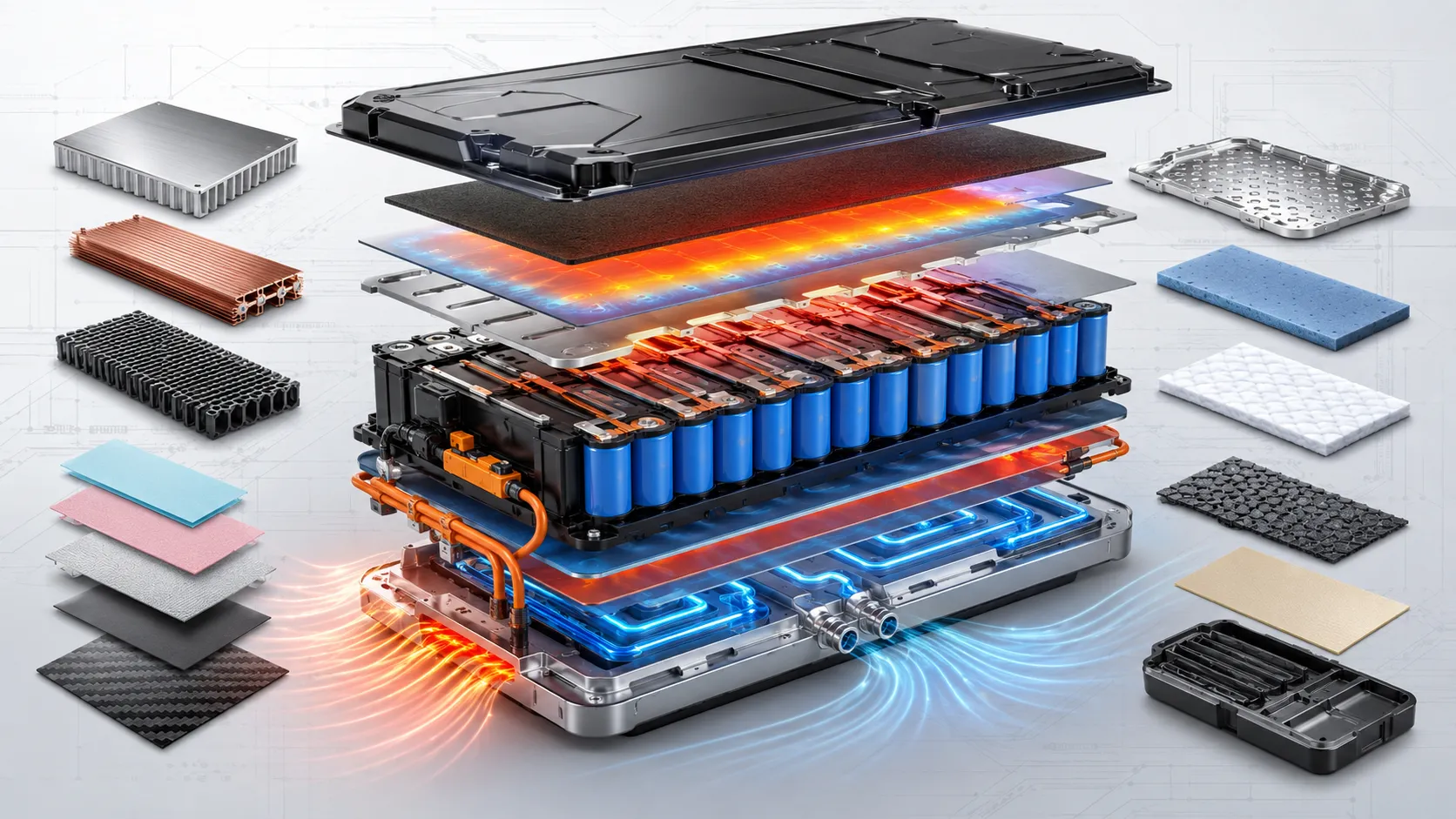
Selecting Thermal Interface Materials (TIMs) and Structural Sealants
High-performance thermal interface materials (TIMs) are required to minimize contact resistance between cell surfaces and cold plates, while structural potting compounds isolate thermal runaway events at the cell-to-cell level. Material selection here is often the weak link that limits cooling system performance — a 0.5 mm air gap or degraded TIM can increase thermal resistance by an order of magnitude compared to a 0.1 mm bond line filled with a 3–5 W/m·K material.
Gap Fillers, Thermal Adhesives, and Potting Compounds
Three material families dominate battery thermal interfaces:
- Gap fillers — typically silicone-based pads or dispensable compounds with thermal conductivity of 1–5 W/m·K — fill the air gap between prismatic cell faces and cold plates without creating a permanent bond, allowing for disassembly.
- Thermal adhesives — rigid two-part epoxies or structural acrylics with 1–3 W/m·K — permanently bond cylindrical cells to cooling fins while providing structural support against vibration.
- Thermal potting compounds — polyurethane or silicone encapsulants with 0.5–2 W/m·K — fill the entire void space between cells in a module, simultaneously conducting heat and providing mechanical shock absorption.
When evaluating these materials, we look at more than just bulk thermal conductivity. Dielectric strength matters for high-voltage pack safety, and compressibility matters for accommodating cell breathing and swelling over thousands of cycles. A rigid thermal adhesive that can’t absorb expansion forces can delaminate from the cell can, creating a high-resistance void that becomes a hotspot.
Fire-Resistant Barriers and Thermal Runaway Propagation Prevention
Thermal runaway containment depends on two distinct material functions: heat extraction during normal operation, and fire-resistant isolation during a catastrophic failure. Many TIMs can serve the first role, but the second requires specialized thermal runaway propagation prevention materials such as intumescent mica sheets, aerogel blankets, or ceramic-fiber-reinforced silicone barriers inserted between every cell or every few cells.
What to verify: Buyers should check for official material datasheets certifying UL 94-V0 (flammability resistance), UL 746C (electrical insulation properties), and RoHS/REACH compliance. For potting compounds used in an electric vehicle pack, we also request supplier data on thermal cycling durability: the material must survive thousands of -40°C to +85°C cycles without cracking or losing adhesion. In high-capacity battery packs with thermal management, the combination of a high-thermal-conductivity gap filler on the cold plate side and an intumescent barrier on the inter-cell side gives the best two-layer protection at a reasonable BOM cost.
| Material Type | Thermal Conductivity (W/m·K) | Key Advantage | Limitation |
|---|---|---|---|
| Silicone Gap Filler | 1–5 | Compressible, disassembly-friendly | May require mechanical pressure fixture |
| Thermal Adhesive | 1–3 | Structural bond + heat transfer | Permanent assembly; harder to service |
| PU Potting Compound | 0.5–2 | Vibration dampening, cell-level encapsulation | Lower thermal conductivity than gap fillers |
| Aerogel/Mica Barrier | <1 | Flame barrier; thermal runaway propagation arrest | Poor thermal conductor; requires parallel cooling path |
Note: Thermal conductivity values are typical ranges; exact performance must be verified under actual contact pressure and bond line thickness conditions.
Pack-Level Simulation, Control Logic, and Hardware-in-the-Loop (HIL) Testing
Computational fluid dynamics (CFD) paired with Hardware-in-the-Loop (HIL) simulation allows engineers to optimize dynamic cooling loop controls, reducing parasitic energy consumption while ensuring rapid thermal response. We’ve seen that skipping HIL validation regularly results in a control loop that responds well on the bench but oscillates or over-cools under real-world pulsed load profiles.
Thermal Modeling and Computational Fluid Dynamics (CFD)
A reliable BMS thermal monitoring strategy starts with a multi-step modeling workflow: first, characterize each cell’s heat generation as a function of SOC, temperature, and C-rate; then build a lumped parameter thermal network that captures heat paths from cell core to external cooling surface; then integrate that network into a 3D CFD model of the pack to predict flow distribution and temperature contours. The CFD model should validate that no dead zones exist where coolant velocity drops below 0.1 m/s, which creates stagnant hot pockets even if average outlet temperature looks acceptable.
Closed-Loop Control Algorithms and Hardware-in-the-Loop Validation
The BMS implements a closed-loop control algorithm — typically a PID controller or, in more advanced systems, a model-predictive control (MPC) algorithm — that modulates pump speed, fan duty cycle, or compressor output based on real-time cell temperature readings. The gains must be tuned for the specific thermal time constant of the pack: too aggressive and the system oscillates; too sluggish and it can’t catch a fast temperature rise during a 3C pulse.
HIL testing connects the real BMS controller hardware to a virtual pack model running in real time on a simulator. This lets us inject fault scenarios — a clogged cooling channel, a failed pump, an ambient temperature spike — and confirm that the control algorithm responds correctly before any physical prototype exists. It’s the only practical way to validate thermal management logic for edge cases that would be dangerous or destructive to create in a real pack.
System Trade-offs, Parasitic Power, and Lifecycle Total Cost of Ownership (TCO)
System design must balance high thermal performance against the parasitic load of the BTMS, as inefficient cooling loops can consume up to 10% of total pack energy capacity during heavy-use cycles. That directly subtracts from usable runtime and adds to the total energy cost over a 10-year deployment.
Parasitic Energy Demands of Active Cooling Loops
Pumps, fans, and refrigerant compressors all draw from the same battery they are designed to protect. A poorly optimized cold plate loop with a 50 W pump running continuously consumes 1.2 kWh per day — equivalent to 438 kWh per year — which for a 5 kWh stationary storage pack translates into a 9% annual energy penalty. Pump sizing must match the actual hydraulic resistance of the loop; oversizing pumps to cover worst-case pressure drops that only occur during brief fast-charge pulses wastes significant energy during float operation.
- Fan-based air cooling: typical parasitic loads of 20–100 W per module
- Liquid pump loop: 30–200 W depending on flow rate and system head loss
- Refrigerant compressor: 200–800 W, with duty-cycle-dependent energy use
The engineering solution is variable-speed control driven by a predictive thermal model that ramps cooling only when cell temperatures approach the upper threshold, rather than running at constant worst-case speed.
Long-Term System Reliability, Maintenance, and Fluid Degradation
Ten-year TCO isn’t just about upfront cost. We’ve pulled apart aged packs where ethylene glycol–water coolant had degraded into acidic byproducts that corroded aluminum cooling plates from the inside, causing pinhole leaks that went unnoticed until a cell bank shorted. Coolant chemistry and corrosion inhibitor packages must be matched to the specific cold plate alloy, and coolant replacement intervals must be part of any OEM maintenance schedule.
Other long-term degradation paths include:
- Pump bearing wear — mechanical pumps have a finite service life, typically 20,000–50,000 hours
- Gasket and O-ring compression set — causing slow weepage that reduces coolant level over 5–7 years
- TIM pump-out — thermal paste pumping out from the bond line under cyclic compression, increasing contact resistance by 30–50% over 3,000 thermal cycles
A realistic TCO analysis should include preventive maintenance — coolant flushes at year 3 and year 7, gasket inspection at year 5, and TIM replacement scenarios — rather than assuming zero maintenance over the life of the asset.
Decision Matrix and Supplier Procurement Checklist
Procurement teams must audit potential battery thermal management suppliers against rigorous mechanical, environmental, and thermal validation standards to avoid costly field recalls. A contract manufacturer quoting the lowest price on a cold plate assembly often doesn’t include the quality documentation, material traceability, or test reports that serious volume buyers need before signing off on a multi-year supply agreement.
Application-Fit Matrix: EV, Grid Storage, and Industrial Equipment
Thermal management requirements diverge sharply by application. In an EV pack, weight and volume constraints push engineers toward high-heat-transfer solutions even with moderate parasitic cost. In grid storage, capital efficiency and low maintenance dominate, since weight and volume are far less critical. Industrial equipment packs often face high-vibration and chemical exposure environments that add durability requirements on top of thermal performance.
| Application | Dominant Thermal Load | Recommended BTMS Type | Critical Design Constraint | Supplier Verification Point |
|---|---|---|---|---|
| Electric Vehicle (4C fast-charge) | High pulse heat during fast charge | Indirect liquid cold plate or direct immersion | Cell-to-cell delta-T under 3°C during charging | Cold plate pressure drop and flow uniformity data across full stack |
| Grid Storage (0.5C–1C) | Low continuous heat over long calendar life | Passive or low-power forced air; optional liquid | 20-year calendar life with zero coolant maintenance | Corrosion test reports for coolant/cold plate combination over 15 years accelerated aging |
| Industrial AGV/Robotics (2C–3C pulses) | Intermittent high-rate discharge | Active air or compact indirect liquid | Shock/vibration resilience for TIM bond line | Vibration test results (IEC 60068-2-64) with thermal cycling superimposed |
| Aerospace/UAV (5C–10C short bursts) | Extreme heat flux for seconds | Direct immersion with minimal mass penalty | System weight below 1.5 kg/kWh for thermal subsystem | Dielectric fluid outgassing and low-pressure altitude chamber data |
Note: Application recommendations are generalized; actual selection requires load-cycle-specific thermal analysis.
For extreme high-rate applications like 5C discharge thermal management in UAV packs, the mass penalty of an active liquid loop can be a dealbreaker if direct immersion is not feasible due to sealing complexity. In those cases, we work with engineers to model whether short-duration burst cooling using PCM and integrated heat spreaders can shave the peak temperature rise enough to stay within cell limits.
OEM Sourcing and Technical Supplier Evaluation Framework
Before engaging a thermal system supplier, procurement teams should assemble a specification package that goes well beyond a top-level wattage requirement. We recommend having these items ready:
- Cell thermal characterization curves (heat generation vs. SOC and C-rate) for the specific cell model
- Pack geometry constraints: maximum external dimensions, mounting point locations, cell spacing tolerance
- Environmental operating envelope: ambient temperature range, humidity, vibration profile
- Coolant type constraints: whether water-glycol, dielectric fluid, or refrigerant is allowed by facility safety codes
- Target cell-to-cell delta-T and maximum cell temperature at worst-case cycle condition
- Regulatory certifications required for the end market: UN 38.3, ISO 26262 functional safety, IP67/IP69K sealing, and IATF 16949 QMS for automotive
Additionally, ask suppliers for:
- Thermal resistance curves for any proposed cold plate assembly at your specific flow rate range
- Dielectric breakdown voltage data under cyclic thermal strain for potting compounds
- Helium leak test results or hydrostatic pressure test reports for coolant plate weld integrity
- Material datasheets certifying UL 94-V0, UL 746C, and RoHS/REACH compliance
- Evidence of a certified QMS — ISO 9001 minimum, IATF 16949 for automotive-grade packs
A supplier who can’t produce these documents early in an RFQ process will typically be unable to meet the reliability and safety requirements of a production-intent thermal system, regardless of their per-unit price. For packs destined for UAV applications, thermal management in UAV battery packs places extreme simultaneous demands on weight, altitude tolerance, and thermal response, making documentation rigor even more critical.
Collaborative Thermal Engineering: Customizing Your Battery Pack Cooling System
Successful pack design requires early integration of thermal management into the mechanical cell arrangement rather than treating cooling as an afterthought. We’ve worked on too many projects where the cell layout was finalized first and the cold plate added later, forcing compromised flow paths that could never fully recover thermal uniformity.
When we partner with an OEM or systems integrator, the initial collaborative phase centers on a few critical inputs. You’ll need to share the cell chemistry (LFP, NMC, LTO) and target cycle life, because thermal stability differences between chemistries drive different cooling thresholds. You’ll also need to define the peak continuous and pulse C-rates, the physical envelope constraints, and any environmental extremes like altitude or submersion. From there, we run custom thermal management solutions analysis using our in-house CFD toolchain to map cell temperatures across the projected duty cycle and identify which cooling topology — passive, forced air, indirect liquid, or immersion — can meet the delta-T target within the mass budget.
This isn’t a catalog-pick exercise. The final design is a co-developed system where cell spacing, busbar routing, structural frame, and thermal loop are interdependent, and the BMS control logic is tuned to that specific hardware. If you’re evaluating thermal partners, look for an engineering team that asks about your load profile and degradation targets before quoting a cost, because that’s the difference between a supplier who sells parts and one who solves thermal problems.
Frequently Asked Questions
What is the ideal temperature range for thermal management in battery packs?
The widely accepted optimal range is 15°C to 35°C during operation, with charging restricted to above 0°C for most lithium-ion chemistries. Staying within this window maximizes round-trip efficiency, limits calendar aging, and keeps the pack well below thermal runaway initiation thresholds.
How does liquid cold plate cooling compare to direct immersion cooling?
Cold plate cooling uses a water-glycol mixture circulated through thermally conductive plates in contact with cells, offering a mature, mechanically simple solution with moderate heat transfer coefficients. Direct immersion submerges cells in a dielectric fluid, providing significantly higher and more uniform heat transfer but requiring demanding enclosure sealing and material compatibility validation across the system’s life.
What are the main disadvantages of active battery thermal management systems?
Active systems impose parasitic power drain on the battery (pumps, fans, compressors), add mass and mechanical complexity, and introduce failure points such as pump wear, gasket leaks, and coolant degradation that require scheduled maintenance throughout the pack’s operational life.
How do thermal interface materials (TIMs) mitigate thermal runaway propagation?
TIMs remove heat from cells during normal operation to prevent local overheating, while dedicated fire-resistant barrier materials placed between cells physically isolate a failed cell’s heat, preventing it from igniting adjacent cells. The combination reduces the risk of cascading thermal runaway across an entire module.
Why are thermal management requirements different for LFP vs. NMC chemistries?
Lithium iron phosphate (LFP) is chemically more stable at high temperatures but becomes far more sensitive to charging damage below 0°C, requiring active heating in cold conditions. NMC cells demand tighter thermal monitoring because their thermal runaway onset temperature is lower, making rapid heat extraction essential under fault conditions. Both chemistries demand precise thermal management, but the failure thresholds and critical operating zones differ.
Frequently Asked Questions
Get a Fast, Custom Power Quote