Battery Management System (BMS) Selection & B2B Design Guide
We’ve seen too many commercial battery packs fail not because the cells were defective, but because the battery management system (BMS) couldn’t handle real-world thermal stress or sensor drift. Selecting the right BMS isn’t about ticking a spec sheet—it’s about ensuring that your entire energy storage system (ESS) or electric vehicle fleet operates safely and cost-effectively for a decade.
This guide lays out the engineering trade-offs, procurement criteria, and integration checkpoints our team uses when helping industrial clients choose a BMS that matches their application, chemistry, and lifecycle expectations.
What is a Battery Management System (BMS) and How Does It Work?
A battery management system (BMS) is a dedicated electronic control unit that monitors, balances, and protects a multi-cell battery pack, acting as the critical interface between the chemical battery cells and the external power load. Far more than a simple protection circuit, it performs real-time state estimation and enforces operating limits to prevent unsafe conditions.
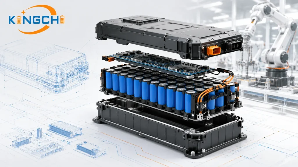
Core Architecture: The “Brain” of the Battery Pack
At the hardware level, a BMS resides on a printed circuit board (PCB) populated with a microcontroller, analog front-end (AFE) ICs, current sensors, and communication transceivers. The AFE digitizes per-cell voltage and temperature readings, while a shunt or Hall-effect sensor tracks pack current. The microcontroller runs firmware that interprets this raw data, computes state estimates, and drives protection MOSFETs or contactors. This architecture separates a true BMS from a basic protection circuit module (PCM), which typically lacks programmable logic and data-logging capabilities.
In our design work, we see the biggest differentiator being the BMS’s ability to adapt to the specific battery chemistry. A BMS-integrated product must be parameterized with the cell’s charge/discharge curves, voltage limits, and temperature coefficients—a one-size-fits-all approach leads to early degradation.
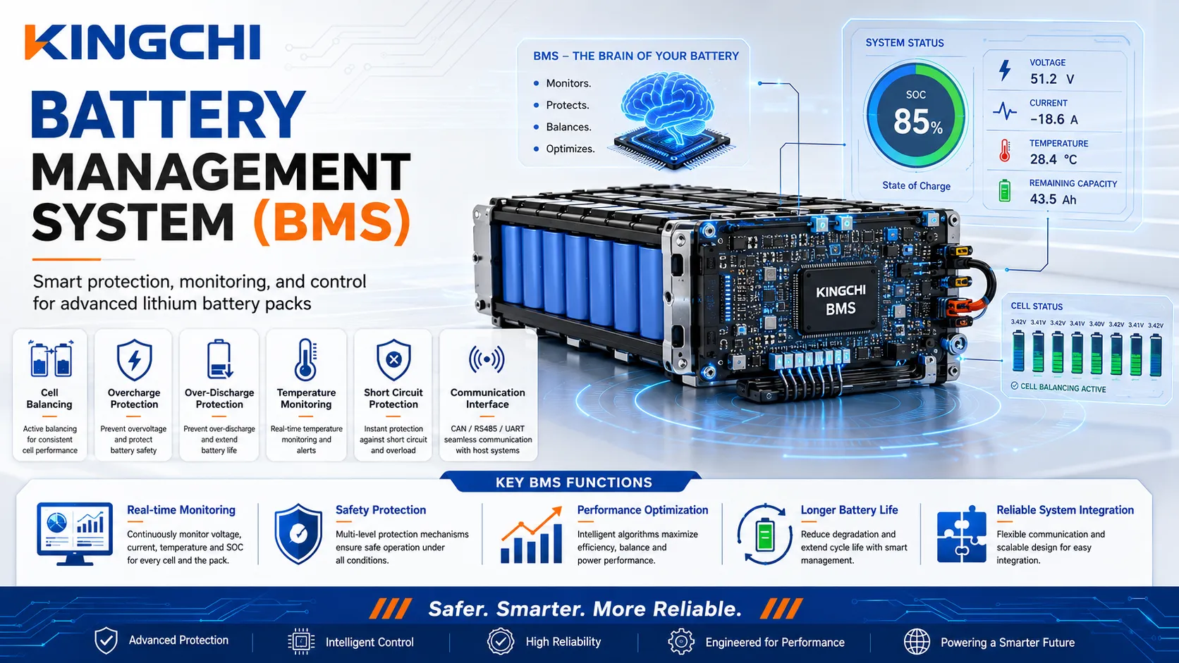
Functional Scope: Monitor, Protect, and Optimize
A commercial-grade BMS performs three primary functions:
- Monitoring: Continuous measurement of cell voltages, pack current, and multi-point temperatures.
- Protection: Disconnecting the pack under overvoltage, undervoltage, overcurrent, short-circuit, or overtemperature faults.
- Optimization: Cell balancing, state-of-charge tracking, and health diagnostics to maximize usable capacity and lifespan.
Real-Time Data Acquisition vs. State Estimation
The BMS samples analog signals at kilohertz rates to catch fast transients, but the true intelligence lies in state estimation algorithms. Using Kalman filtering or coulomb counting (often refined with neural network models, as explored in MATLAB/Simulink environments), the system fuses noisy sensor data into reliable state of charge (SOC) and state of health (SOH) values. This estimation must remain accurate even as components age and sensors drift.
Critical Functions of a Battery Management System in Commercial Applications
For commercial applications, a battery management system provides safety, performance optimization, and operational longevity by constantly running state estimation algorithms and thermal monitoring. It is the only layer that prevents a single-cell anomaly from cascading into a pack-level catastrophe.
State of Charge (SOC) and State of Health (SOH) Estimation
State of charge (SOC) tells the user how much energy remains, while state of health (SOH) quantifies irreversible capacity fade. Accurate SOC prevents both over-discharge and premature shutdown, and accurate SOH lets fleet managers schedule replacements before failures. Modern BMS designs implement adaptive algorithms that learn the cell’s aging characteristics over time. Without this, a pack’s usable window shrinks artificially, wasting capital.
Engineering takeaway: We demand SOC accuracy better than 5% across the full temperature range for any BMS deployed in critical backup or mobility applications. Anything less invites range anxiety or downtime.
Thermal Management and Thermal Runaway Prevention
Thermal runaway begins when a cell’s internal temperature rise becomes self-sustaining. A BMS counters this by embedding multiple thermistors or thermocouples per module and executing a multi-tier response: first, derating charge/discharge current; next, commanding active cooling (fans, liquid loops); finally, opening contactors to isolate the pack. For lightweight UAV battery packs that push cells to their thermal limits, this response must execute in milliseconds.
In stationary ESS deployments, we often integrate the BMS with a site-level energy management controller that can preemptively shed load if temperature trends exceed safety thresholds. The BMS data link becomes a fire-prevention tool, not just a monitor.
Overcurrent and Overvoltage Protection Circuits
Overvoltage protection is non-negotiable. If a Li-ion cell exceeds its maximum voltage—typically 4.2 V for NMC, 3.65 V for LiFePO4—electrolyte decomposition accelerates, creating gas and heat. The BMS must open the charge path within microseconds of detecting an overvoltage event. Similarly, overcurrent protection prevents conductor overheating and cell damage during short circuits or motor stall conditions. For BMS for high-discharge applications, we pay extra attention to the precision of the current-sense resistor and the latency of the comparator circuit.

Cell Balancing Technologies: Active vs. Passive Balancing
A key architectural decision when specifying a battery management system is selecting between passive balancing, which dissipates excess charge as heat, and active balancing, which redistributes energy from high-charge to low-charge cells to maximize pack capacity. The right choice hinges on duty cycle, pack cost sensitivity, and thermal budget.
Passive Balancing: Cost-Effective Dissipative Methods
Passive balancing switches a bleed resistor across the highest-voltage cells, burning small amounts of energy until all cells align. It’s simple, inexpensive, and perfectly adequate for low-rate applications where balancing currents of 50–150 mA suffice. However, the generated heat must be managed. In sealed enclosures, repeated balancing cycles can raise internal temperatures enough to accelerate aging.
Buyer warning: Verify if the BMS’s thermal dissipation design can handle continuous passive balancing during high-current charging. We’ve seen packs where the resistors overheated and the PCB discolored after a few dozen cycles.
Active Balancing: Bidirectional Energy Redistribution
Active balancing uses switched-capacitor or inductor-based converters to shuttle energy between cells, achieving efficiencies above 90%. This minimizes waste heat and supports balancing currents of several amperes, making it ideal for high-capacity packs that see deep daily cycling. The trade-off is increased component count, board space, and firmware complexity.
In our experience, active balancing pays off when the pack’s replacement cost exceeds the incremental BMS cost, or when thermal management is already a challenge—such as in sealed outdoor ESS cabinets.
Impact of Balancing Efficiency on Battery Pack Lifespan
Regardless of method, effective cell balancing prevents capacity walk-down, where a single weak cell forces the entire string to operate within a shrinking voltage window. Without balancing, voltage divergence grows with each cycle, cutting usable capacity. A well-tuned balancing algorithm can keep cell voltage spread below 10 mV, preserving up to 99% of theoretical pack capacity over thousands of cycles.
| Feature | Passive Balancing | Active Balancing | Best Use Case |
|---|---|---|---|
| Mechanism | Resistive bleed | Energy transfer (capacitive/inductive) | — |
| Energy Efficiency | 0% (waste heat) | 90-95% | — |
| Heat Generation | Moderate to high | Low | — |
| Cost per Cell | Low | 3-5× higher | — |
| Complexity | Simple resistor + switch | Converter + control loop | — |
| Typical Balancing Current | 50–200 mA | 1–5 A | — |
| Impact on Lifespan | Good for low-cycle apps | Extends capacity retention in deep-cycle use | — |
Note: Balancing current specifications must be matched to pack capacity and charge rate. Verify actual balancing current under worst-case cell voltage divergence with your supplier.
Key BMS Topologies: Centralized, Daisy-Chained, and Distributed Architectures
The choice of BMS topology—centralized, daisy-chained, or distributed—directly impacts assembly costs, system scalability, and wiring complexity in high-voltage B2B battery systems. Each topology suits different pack voltages and mechanical constraints.
Centralized BMS Topology for Low-Voltage Packs
A single PCB hosts all sensing and control, with long wire harnesses running to each cell. This keeps component count low but becomes unwieldy above roughly 48 V due to voltage drop, noise pick-up, and safety risks from high common-mode voltages. It’s best for small specialty packs where simplicity wins.
Daisy-Chained (Modular) BMS for Scalable Applications
Individual slave modules sit next to cell groups, communicating over a noise-immune CAN bus or isoSPI link to a master controller. This modular approach slashes harness weight, isolates hazardous voltages, and allows the same slave design to be reused across different pack configurations. We commonly recommend it for BMS in AGV battery packs and mid-sized industrial vehicles, where serviceability matters.
Distributed BMS for High-Voltage Utility-Scale ESS
In megawatt-hour energy storage systems (ESS), distributed topologies place intelligent monitoring chips directly on each cell or module, sometimes with wireless links. This yields the highest redundancy and the simplest cabling, but demands robust firmware and thorough EMC qualification. Our custom BMS solutions for utility-scale projects often adopt a distributed architecture to meet uptime and safety certifications.
| Parameter | Centralized | Daisy-Chained/Modular | Distributed |
|---|---|---|---|
| Architecture | Single PCB | Slave boards + master | Per-cell/module nodes |
| Wiring Complexity | High (long harnesses) | Low | Minimal |
| Scalability | Limited to ~48 V | Excellent up to 1000 V | Virtually unlimited |
| Cost per Cell | Lowest | Moderate | Higher upfront |
| Isolation | None | Galvanic isolation between modules | Full isolation |
| Typical Voltage Range | 12–48 V | 48–800 V | 400 V–1500 V |
| Best Application | Light electric vehicles, small robotics | AGVs, forklifts, residential ESS | Utility ESS, marine, grid storage |
Note: Topology choice also affects firmware update logistics and field diagnostic capability. Daisy-chained and distributed systems allow per-module firmware flashing, reducing service downtime.
Technical Specification Trade-Offs in Commercial Environments
Specifying a battery management system requires balancing sensor precision, quiescent current draw, and electromagnetic noise immunity against unit budget constraints. Cutting corners on any of these creates hidden costs that surface only after deployment.
Sensor Accuracy and Drift over Operational Lifespans
Cell voltage measurement accuracy directly dictates how tightly the pack can be utilized. A ±2 mV AFE allows charging cells to their true maximum without overshoot; a ±10 mV AFE forces the designer to leave a wider safety margin, effectively throwing away capacity. Over thousands of hours, sensor drift compounds this error. We have evaluated BMS units where the voltage reference shifted by 15 mV after 18 months, causing the balancer to over-discharge weak cells. Always request the supplier’s drift specification across temperature and time.
Standby Current Draw and Battery Self-Discharge
Even when a pack sits idle, the BMS consumes power to keep its microcontroller alive and communication links listening. If the standby draw is 5 mA on a 10 Ah 48 V string, the BMS alone will fully deplete the pack in under 3 months. For seasonal equipment, low quiescent current (ideally <100 µA in ship mode) is critical. We often specify a hardware wake-up signal or a manual disconnect to eliminate parasitic drain during storage.
Electromagnetic Compatibility (EMC) in High-Noise Environments
Industrial drives, inverters, and contactors radiate interference that can corrupt analog sensor readings or trigger false undervoltage trips. Decision rule: High-power industrial environments require an isolated CAN bus with robust common-mode filtering on the printed circuit board (PCB). We also recommend adding ferrite beads, differential routing for critical signals, and metal shielding over the AFE. Without these measures, a BMS that passes bench tests may fail repeatedly on a factory floor.
B2B Procurement Criteria: Selecting a BMS for Industrial Systems
Procurement teams should evaluate a battery management system based on its chemistry optimization, compatibility with existing industrial communication protocols, and physical environmental resilience. These three axes separate a robust BMS from a generic board that will cause support headaches later.
Matching Cell Chemistry: LiFePO4, NMC, and LTO Requirements
A BMS configured for NMC cannot safely manage a LiFePO4 pack without extensive re-parameterization. Voltage thresholds—overvoltage, undervoltage, recovery—differ by chemistry, and charge termination algorithms (CC-CV vs. pulse) vary. Even within the same chemistry, variations in electrode formulation shift the OCV-SOC curve. When integrating BMS into custom battery packs, we always load chemistry-specific lookup tables and validate them with cycling data from the exact cell lot being used.
What to verify: Confirm that the BMS firmware allows full calibration of all protection setpoints via a configuration tool, not hard-coded values. This is essential if you might qualify a second-source cell in the future.
Communication Protocols: CAN bus, Modbus, and SMBus Integration
Industrial systems overwhelmingly rely on CAN bus (ISO 11898) for real-time control, while stationary storage often uses Modbus RTU/TCP for SCADA integration. SMBus and I2C appear in lighter applications such as medical carts or small UPS units. A BMS that offers only a single protocol limits its deployability. We look for BMS units with dual CAN ports and an RS485 Modbus interface, enabling them to bridge vehicle and stationary use cases without external gateways. Smart charging with BMS also requires the BMS to communicate with BMS-compatible chargers to adjust current limits dynamically.
Physical Durability, Environmental Ratings, and IP Standards
For outdoor ESS or mobile machinery, the BMS enclosure must withstand moisture, dust, and vibration. At a minimum, we specify IP67 for exposed modules and conformal coating on the PCB. In tactical vehicle power supplies, the BMS must also survive shock loads exceeding 15 G and broad temperature swings from -40°C to +85°C. Low-temperature battery management becomes especially challenging, because the BMS must prevent charging below 0°C for Li-ion cells while still allowing discharge—requiring both accurate temperature sensing and firmware-enforced charge inhibition.

Total Cost of Ownership (TCO) and Lifecycle Economics of BMS Integration
Although high-reliability, software-rich battery management systems carry a premium initial cost, they reduce total cost of ownership by extending pack service life and preventing catastrophic field failures. The BMS is not where engineers should hunt for the last dollar of savings.
Initial Hardware Capex vs. Long-Term Maintenance Opex
A basic passive-balancing BMS may cost $30–50 per module, while an active-balancing unit with isolated CAN and data logging can reach $150–250. Over a 10-year pack life, the latter often eliminates one or two complete pack replacements by keeping cells balanced and logging degradation trends. Factor in the labor for on-site troubleshooting, and the premium evaporates. We advise customers to build a TCO model that includes pack replacement cost, downtime, and remote diagnostics, not just BMS purchase price.
How Advanced State Estimation Prevents Premature Pack Replacement
When a BMS reports an incorrect SOC or fails to track SOH, fleet operators retire packs based on runtime symptoms rather than data. Accurate SOH estimation allows stretching a pack’s useful life by 20% or more, redeploying it to less demanding roles instead of scrapping it. This requires the BMS to log cycle counts, cumulative energy throughput, and internal resistance trends—capabilities absent from low-cost PCMs.
Mitigating the Cost of Field Failures and System Recalls
The worst financial outcome is a field recall triggered by a safety incident. A BMS that lacks non-volatile event logging leaves no forensic trail. When a returned pack shows no obvious damage, without a data record the root cause remains unknown, forcing the manufacturer to recall entire batches unnecessarily. We emphasize in our BMS sourcing considerations that the BMS must timestamp and store at least the last 50 protection events. This data pays for itself the first time it avoids a recall.
Buyer warning: A cheap BMS without robust history-logging capabilities makes post-mortem diagnostics nearly impossible, driving up warranty costs and eroding customer trust.
Specification Comparison Matrix: Evaluating BMS Candidates
Before finalizing a supplier, engineering teams must evaluate BMS specifications across a structured performance matrix prioritizing cell-sensing accuracy, safety certifications, and integration flexibility. This matrix serves as a standard for comparing multiple vendors side by side.
Key Performance Metrics for B2B Evaluation
The following table captures the parameters we consider when vetting a BMS for industrial-grade lithium battery packs with BMS. These values are representative of high-quality BMS designs, but every spec must be validated against the actual cell and application.
| Specification Parameter | Minimum Acceptable | Kingchi Preferred | Verification Note |
|---|---|---|---|
| Cell Voltage Sensing Accuracy | ±10 mV | ±2 mV | Verify across -20°C to +60°C |
| Overvoltage Protection Threshold Accuracy | ±15 mV | ±5 mV | Check response time < 1 ms |
| Undervoltage Protection Threshold Accuracy | ±15 mV | ±5 mV | Should be configurable per chemistry |
| Max Continuous Current | 1× nominal pack rating | 1.5× nominal | Verify thermal derating curve |
| Peak Current (10 s) | 2× nominal | 3× nominal | Must not trip premature |
| Communication Ports | 1× CAN | 2× CAN + RS485 | Check for galvanic isolation |
| Safety Certifications | CE, UL 1973 Recognized | IEC 62619, UN 38.3, ISO 26262 ASIL C | Request test reports, not just certificates |
| Operating Temperature Range | -10°C to +50°C | -40°C to +85°C | Verify function, not just survival |
| IP Rating | IP55 | IP67 with conformal coating | Check connector ingress protection |
Note: All listed specifications should be verified with the supplier using the actual cell chemistry and pack configuration. Certifications like UN38.3 compliance for BMS and IEC 62619 must be validated with the latest test reports.
Safety Standards and Regulatory Compliance to Verify
Industrial BMS must align with application-specific standards. For stationary ESS, UL 1973 and IEC 62619 are baseline. For automotive, ISO 26262 functional safety requirements drive hardware redundancy and fault-tolerant firmware. We also expect the BMS to support cell-level temperature monitoring coverage for UN 38.3 transportation testing. Buyers should request a compliance matrix, not assume that a CE mark covers all regions.
The Operational Readiness Checklist
Before commissioning a BMS in a fleet or ESS, verify these items:
- All cell voltage and temperature channels read within calibration limits.
- Overvoltage, undervoltage, and overtemperature thresholds are configured to the specific cell datasheet.
- Communication interfaces (CAN, Modbus) are tested with the actual host controller at the required baud rate and termination.
- Data logging functionality captures and timestamps all fault events.
- Balancing circuit turns on at the correct voltage and does not overheat in continuous operation.
- Standby current in ship mode is measured and confirmed under worst-case temperature.
- EMC immunity is validated on-site with the final power electronics in place.
Optimizing Your Power Systems: Partnering with a Technical BMS Supplier
Transitioning from standard battery packs to a fully optimized, smart-powered fleet or ESS requires collaborative engineering and precise BMS selection. A supplier that only ships a PCB is not enough—you need a partner who understands how your pack will age in the field.
We recommend preparing the following before engaging with our engineering team:
- Average and peak load profiles (duty cycle).
- Cell configuration (e.g., 16S, 48S, parallel strings).
- Target cell chemistry and manufacturer part number.
- Required communication protocol (CAN 2.0B, CAN FD, Modbus TCP).
- Environmental temperature range and IP requirement.
- Any functional safety goals (e.g., ASIL B, SIL 2).
With these inputs, we can map out the optimal BMS topology, balancing strategy, and firmware parameter set that will maximize your pack’s safety and life. Explore industry-specific battery management design examples or contact us to discuss a custom integration.
Frequently Asked Questions
What is the main purpose of a battery management system (BMS)?
The main purpose is protecting the battery pack from unsafe electrical and thermal conditions, tracking state of charge and state of health, and maximizing lifecycle performance through balancing and optimized charge control.
Can you run a lithium battery without a BMS?
While chemically possible, operating a lithium battery without a BMS is extremely unsafe for commercial or industrial applications. It risks overcharge, deep discharge, and thermal runaway, leading to fire and rapid cell degradation.
What is the difference between active and passive cell balancing in a BMS?
Passive balancing burns excess energy as heat through resistors, while active balancing transfers energy from higher-charged cells to lower-charged cells using efficient converter circuits, preserving more pack capacity and generating less waste heat.
How does a battery management system prevent thermal runaway?
The BMS constantly monitors multiple temperature sensors, and when thresholds are approached, it reduces charge/discharge current, activates cooling systems, and ultimately opens contactors to isolate the pack before runaway can propagate.
Which communication protocols do industrial battery management systems use?
Industrial BMS commonly uses CAN bus (automotive and heavy machinery), Modbus RTU/TCP (stationary energy storage and SCADA), and SMBus/I2C (light commercial equipment). Multi-protocol support is preferred for versatility.
What safety standards should a commercial battery management system meet?
Key standards to verify include UL 1973 for stationary batteries, IEC 62619 for industrial applications, UN 38.3 for transport safety, and ISO 26262 for functional safety in automotive contexts, depending on your deployment.
Frequently Asked Questions
Get a Fast, Custom Power Quote