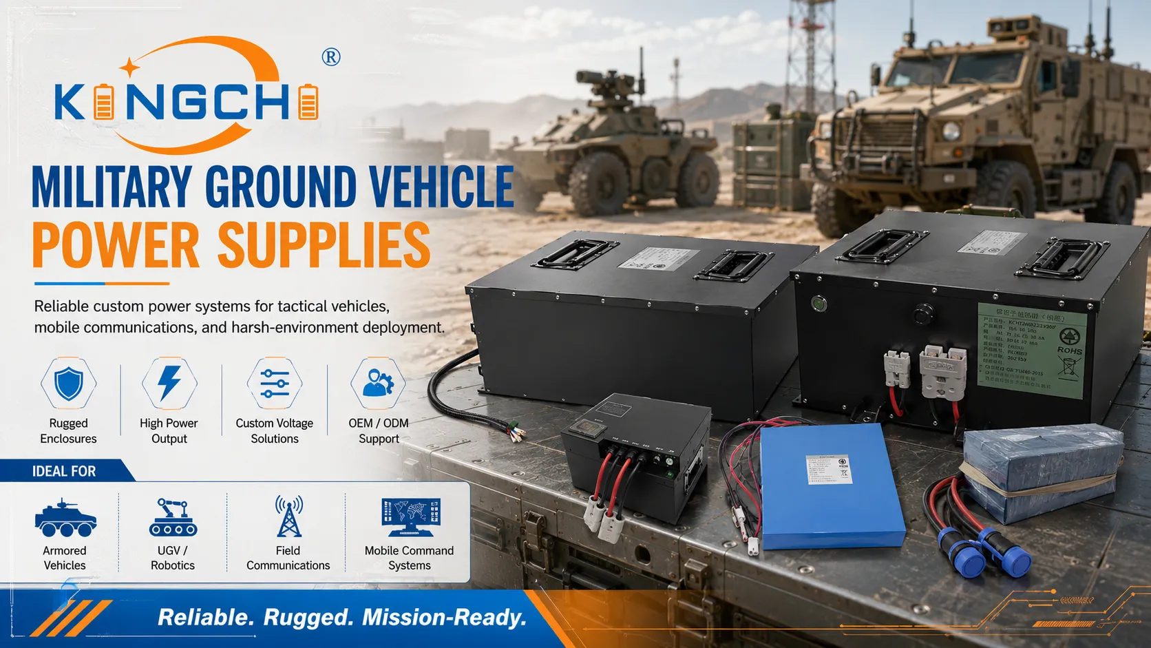
Tactical Ground Vehicles Power Supplies & Vetronics Solutions
Most procurement teams treat MIL-STD-1275 compliance as a checkbox. The real engineering challenge comes when a 28V vehicle bus spikes to 100V during load dump or droops below 18V during engine cranking. We’ve seen designs that passed bench tests fail hard on a running Abrams or LAV because the power supply couldn’t ride through transients and EMI that aren’t on the spec sheet.
The first filter for any tactical ground vehicles power supplies is not the rated output watts; it’s how the unit handles the electrical hell of a live military 28V DC system. Specifically as defined by the MIL-STD-1275 power supply standard.
Critical Technical Specifications and Military Standards (MIL-STD-1275)
Navigating MIL-STD-1275 Compliance for Spikes and Surges
MIL-STD-1275 defines the interface between a military vehicle’s electrical system and the electronic equipment it powers. The standard spells out specific surge, spike, and ripple limits that a power supply must survive without damage or interruption. When evaluating tactical ground vehicle power supplies, we prioritize input protection circuits that can ride through load-dump transients where voltage can exceed 100V for tens to hundreds of milliseconds. A heavy-duty transient voltage suppressor alone isn’t enough; active clamping and wide‑input front‑end design are what separate a deployable unit from a bench‑top lab supply.
| Transient Event | Typical MIL-STD-1275 Condition | Power Supply Requirement |
|---|---|---|
| Load Dump Surge | Battery disconnect while alternator is running | Withstand 100V for 500 ms (varies by revision) |
| Inductive Spike | Fast‑switching solenoid or relay release | Suppress ±200V transients with sub‑microsecond response |
| Cranking Voltage Sag | Cold engine start under full accessory load | Maintain output regulation down to 12V input for 30 seconds |
Note: Buyers should verify exact waveform requirements against the current MIL-STD-1275 revision applicable to their program.
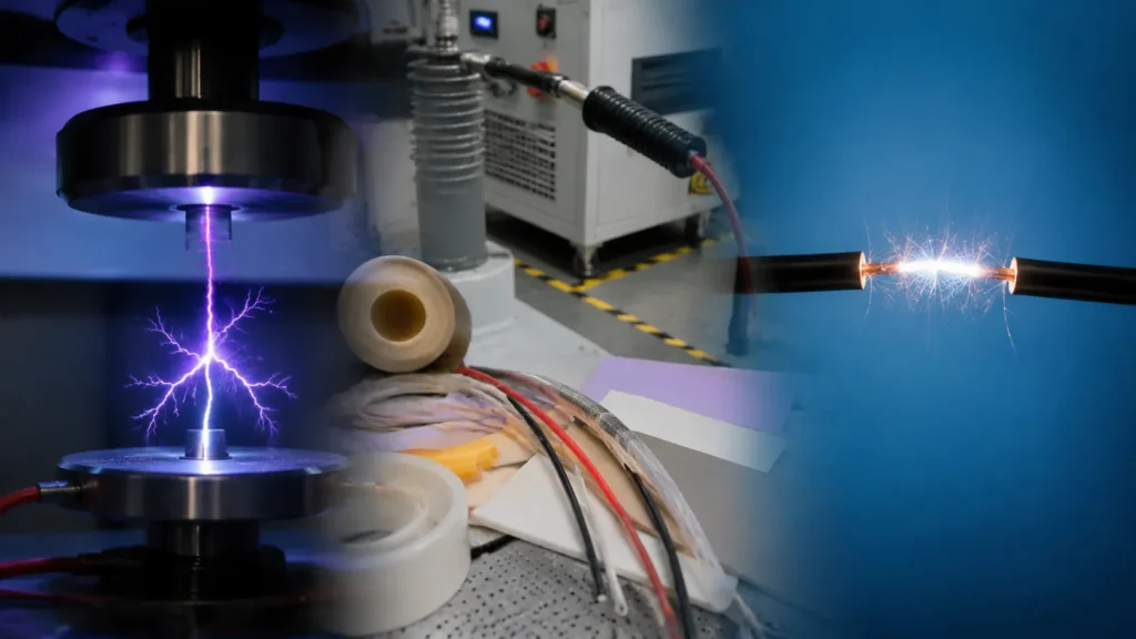
Electromagnetic Interference (EMI) and MIL-STD-461 Requirements
Tactical communications can be disrupted by even low‑level conducted or radiated emissions from a power supply. MIL-STD-461 testing is mandatory. A supply that hasn’t passed CE102 and RE102 limits can desensitize VHF/UHF radios, jam GPS receivers, or cause bit errors in C4ISR networks. We insist on multi‑stage EMI filtering and fully shielded enclosures. Partnering with a military battery pack manufacturer that understands EMI hardening at the system level avoids costly late‑stage integration fixes.
Environmental Ruggedization and MIL-STD-810 Testing
Beyond the electrical interface, the power supply must live inside a sealed armored hull. That means surviving shock, vibration, sand, dust, and rapid thermal swings. Any unit we specify is designed to the relevant MIL-STD-810 methods — not just the chamber test, but the mechanical mounting and connector sealing that keep it operational after repeated 40 G shock pulses. When a project requires non‑standard form factors, we coordinate with suppliers of custom military battery packs to ensure the entire power chain, not just the converter, is hardened to the same environmental profile.
Core Applications of Tactical Vehicle Power Supplies
Powering Vetronics and C4ISR Communication Systems
Vetronics power solutions must clean up the noisy vehicle bus so that sensitive mission computers and multi‑band radios receive stable, low‑noise DC. A typical 28V bus carries ripple, alternator whine, and load‑induced spikes. We design our custom power solutions for ground vehicles with output noise filtering below 50 mV peak‑to‑peak, often with galvanic isolation between input and output channels to break ground loops that plague distributed vetronics architectures.
Auxiliary Power Units (APUs) for Electronic Warfare (EW) Platforms
EW suites, mobile command posts, and jammers operate at kilowatt‑level continuous power, all from the vehicle’s limited alternator and battery reserves. Military-grade power conversion for these applications must deliver 95%+ efficiency to stay within the available SWaP budget while rejecting the intense reverse‑power pulses that some EW antennas induce. We typically specify synchronous rectification topologies and active OR‑ing controllers to maintain a stable DC rail even under aggressive pulsed load conditions.
Tactical Ground Power for Autonomous and Unmanned Ground Vehicles (UGVs)
UGVs sacrifice payload for batteries, so every watt‑hour matters. Lightweight, high‑efficiency DC-DC converters are non‑negotiable. We routinely see programs where replacing a legacy 85%-efficient converter with a 96%-efficient unit adds 20+ minutes to an autonomous mission. In these applications, the power supply also often doubles as a system health monitor, reporting input voltage, temperature, and current draw over a CAN bus to a central autonomy controller.
Engineering Trade-offs: SWaP-C Optimization and Thermal Management
Balancing Size, Weight, and Power (SWaP) Constraints
SWaP optimization is a balancing act. Every extra pound of power supply and thermal management gear directly reduces fuel efficiency or the armor payload the vehicle can carry. We approach it by stacking requirements against available volume and then selecting the highest power‑density topology that still meets thermal and EMI specs. Key trade‑offs we evaluate include:
- Switching frequency vs. EMI: higher frequency shrinks magnetics but increases radiated noise, demanding additional shielding.
- Enclosure material: aluminum offers good conduction and weight, but thicker wall sections eat into internal volume.
- Connector selection: circular military connectors are rugged but heavy, while lighter commercial options may compromise seal integrity.
Passive Conduction Cooling vs. Active Liquid/Fan Cooling
In sealed armored compartments, fan‑cooled supplies are a liability. Dust, water, and debris clog fans, and moving parts create acoustic and mechanical failure points. Conduction cooling — bolting the power supply baseplate directly to a vehicle cold wall or chassis — is the gold standard for tactical reliability. The trade‑off is that the available chassis temperature can reach 85°C in desert conditions, forcing derating. The table below summarizes when each approach makes engineering sense.
| Cooling Method | Engineering Advantage | Primary Limitation | Best For |
|---|---|---|---|
| Passive Conduction | Zero moving parts, fully sealed, silent | Limited by chassis thermal capacity | Sealed vetronics bays, dusty environments |
| Active Fan Cooling | Handles high spot heat densities | Fan failure risk, dust ingress, acoustic signature | Filtered‑air compartments with moderate thermal margins |
| Liquid Cooling | Highest heat removal capacity | Plumbing complexity, pump power, potential leaks | Directed‑energy or high‑power radar systems where passive isn’t sufficient |
Output Configuration Stability (12V, 24V, and 28V DC Architectures)
Rugged DC-DC converters must maintain tight regulation not only at steady state but also during the severe voltage sags that accompany engine cranking. A common pitfall is designing a supply that works at a nominal 28V input but collapses its output the moment the bus dips to 16V during a cold‑start event. We design all tactical DC‑DC stages with a hold‑up time specification (typically 30 ms minimum) and maintain output regulation across a full 2:1 input range to keep downstream loads stable.
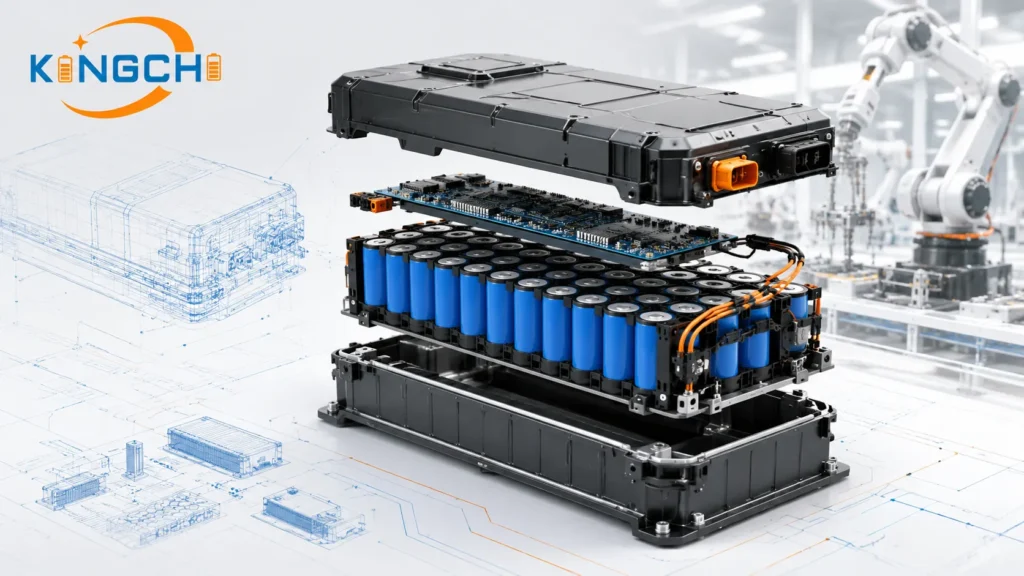
Hybrid Power Integration and Advanced Energy Storage
Incorporating Battery Banks and High-Output Alternators
Modern vehicle power distribution units must seamlessly manage energy flows between high‑output alternators, auxiliary battery banks, and the loads they feed. We frequently integrate high discharge rate batteries into power systems that require short‑duration surge capability beyond what the alternator alone can provide. The power supply’s charger‑interface circuitry must accurately follow lithium‑ion charge profiles and communicate state‑of‑charge data to the vehicle’s battle management system.
Managing Pulsed Loads for Directed Energy and Radar Systems
Pulsed loads — like those from an active electronically scanned array radar or a laser weapon — can draw hundreds of amps for milliseconds, then drop to near zero. Without a buffer, these pulses pull the vehicle DC bus into brownout. We solve this by placing lithium battery packs for tactical vehicles across the DC bus, sized to deliver the peak pulse power while the alternator and converters handle the average load. The power supply controller must include fast‑acting current limiting and bus capacitance management to prevent protection circuitry from prematurely disconnecting the load.
Procurement Strategies: COTS vs. Custom Power Supply Engineering
Evaluating Modified Commercial Off-The-Shelf (COTS) Solutions
Modified COTS can dramatically reduce lead times and non‑recurring engineering costs, provided the base design has enough margin to absorb military‑grade upgrades. We usually start with a COTS supply that already meets the core output power and input voltage range, then add conformal coating, structural potting, upgraded filtering, and qualified connectors. This approach works when the form factor and cooling method are already close to the vehicle’s available envelope. The table below outlines the typical trade‑offs between COTS‑based and full‑custom paths.
| Factor | Modified COTS | Custom Design | Procurement Consideration |
|---|---|---|---|
| Development Lead Time | 3–6 months | 12–18 months | Urgency and program funding timeline |
| NRE Cost | Low to moderate | High | Budget availability for upfront engineering |
| Form Factor Flexibility | Limited; constrained by existing chassis | Full optimization to available volume | Space‑constrained armored platforms |
| Reliability (MTBF) | Depends on base design; may need derating | Designed to specified mission life | Decades‑long vehicle service requirements |
| Standards Compliance | Must be verified post‑ruggedization | Built from ground up to MIL‑STD list | Risk of non‑compliance during qualification |
Note: Actual lead times and costs vary by program; procurement teams should request a detailed compliance matrix and NRE estimate before committing to a path.
When Custom Power Supply Design is Mission-Critical
Programs that demand non‑standard voltage rails, extreme power density (above 200 W/in³), or operation in 105°C ambient coolant temperatures usually leave no COTS option. Same goes for supplies that must survive continuous gun‑fire shock while meeting MIL‑STD‑461 conducted emissions with no shielding room. In these scenarios, we recommend a ground‑up custom design. The upfront NRE is higher, but the lifecycle cost advantage — no derating, no adapters, no field‑modification kits — often justifies the investment over a 20‑year vehicle fleet lifetime.
Key Vendor Selection Criteria for Defense Program Managers
Assessing Lifetime Support, Redundancy, and MTBF Ratings
Tactical vehicles stay in service for decades, and power supplies must be supported for the same horizon. Procurement teams should dig into the vendor’s lifecycle management plan: will the supply be subject to obsolescence after five years, or is there a sustained engineering commitment? Mean Time Between Failure (MTBF) numbers are useful but only when backed by a defined calculation method (MIL‑HDBK‑217F or similar). We advise evaluators to verify:
- Component derating policy (percentage of rated voltage, current, and temperature).
- Design‑for‑reliability reviews and HALT (Highly Accelerated Life Test) results.
- Documented field‑failure data from similar platforms, not just theoretical MTBF.
- Availability of form‑fit‑function replacements for legacy units.
Ensuring Supply Chain Integrity and Quality Certifications
A power supply is only as good as its supply chain. We emphasize full component traceability, counterfeit mitigation processes, and compliance with assembly standards such as IPC‑A‑610 Class 3. When batteries are part of the system, buyers should confirm UN38.3 certification for vehicle batteries is in place. Partnering with top military battery suppliers that maintain AS9100 or ISO 9001 certification and track components at the lot level helps prevent production gaps that can halt vehicle acceptance testing.
Plan Your Tactical Ground Vehicle Power System Deployment
Before reaching out to an engineering team, we suggest assembling a technical requirements checklist. This turns a generic request into actionable design constraints. The most productive conversations start when customers bring clear compliance matrices, target SWaP numbers, and defined environmental envelopes. To prepare, gather the following:
- Steady‑state input voltage range (e.g., 16–36 VDC per MIL‑STD‑1275) and any unusual transient conditions.
- Continuous and peak output power for each voltage rail, with maximum allowable ripple.
- Required efficiency target and cooling interface (conduction plate temperature, available airflow).
- Mechanical dimensions and mounting constraints inside the vehicle bay.
- List of applicable MIL standards (MIL‑STD‑1275, MIL‑STD‑461, MIL‑STD‑810) and the specific test methods needed.
Our approach is engineering‑led. We walk through the requirements, propose a compliance matrix, and explore whether a modified COTS or custom path best balances cost, timeline, and technical risk. Contact us when you have your checklist ready — we’ll take it from there.
Frequently Asked Questions
What is the significance of MIL-STD-1275 in tactical ground vehicle power supplies?
MIL-STD‑1275 is the interface standard that defines voltage transients, operating ranges, and electrical characteristics for equipment connected to military 28V vehicle power systems. It ensures that power supplies can survive surges, spikes, and sags without damaging themselves or connected electronics.
How do DC-DC converters handle starting engine transients in military vehicles?
Rugged converters use wide‑input range designs, active surge suppression, and internal holdup capacitance to ride through the severe voltage drop during engine cranking. They maintain regulated output even when input sags to 12V or lower, preventing downstream reset or brownout.
What are the primary differences between lithium and lead-acid ground power units?
Lithium units offer significantly higher energy density and faster recharge but require more sophisticated battery management. Lead‑acid systems are heavier but more tolerant of extreme temperature abuse and are often preferred for applications where cost and simplicity override weight concerns.
How does thermal performance impact the lifespan of a tactical power supply?
Excess heat accelerates degradation of electrolytic capacitors and semiconductors. Military‑grade supplies rely on conduction cooling to reject heat directly into the vehicle chassis, minimizing internal temperature rise and extending operational life well beyond what fan‑cooled alternatives can achieve.
Can standard commercial power supplies be modified for tactical military use?
Yes. Through conformal coating, structural potting, upgraded filtering, and hardened enclosures, commercial designs can be ruggedized to meet many MIL‑STD requirements. This approach can significantly reduce development costs and lead times when the base supply’s core topology has sufficient margin.
Frequently Asked Questions
Get a Fast, Custom Power Quote