Engineering Guide to Thermal Interface Materials (TIM)
In high-power electronics, less than 1% of a mated interface may actually be in metal-to-metal contact. The rest is air — a near-perfect insulator. Thermal Interface Materials (TIM) are engineered to fill these micro-scale voids, eliminating hot spots and managing junction temperatures that would otherwise degrade performance or cause failure. Without the right TIM, even the most advanced cooling architecture falls short.
Selection is rarely as simple as picking the highest bulk thermal conductivity. An effective TIM must conform to surface roughness under available clamping pressure, maintain a thin bond line without risking dielectric breakdown, and survive cyclic mechanical and thermal stresses. This guide maps the physics, material formats, and engineering trade-offs that drive TIM specification in automotive, telecom, power electronics, and other demanding industries.
The Physics of Interface Heat Transfer: Why TIMs are Critical
Mated solid surfaces touch at only a fraction of their apparent area due to microscopic peaks and valleys (asperities); the remaining gaps are filled with air, which acts as a severe thermal insulator with a conductivity of only ~0.026 W/m·K. TIMs displace this air to establish a continuous, thermally conductive path between the heat source and heat sink.
Microscopic Surface Roughness and Air Entrapment
Even precision-machined surfaces exhibit roughness at the micron scale. When two surfaces are brought together under mechanical load, the actual contact area often amounts to just a few percent of the apparent overlap. The interstitial voids become trapped pockets of air, adding a large thermal resistance that dominates the interface. This contact resistance is the primary barrier that thermal interface materials must overcome, not the bulk material properties of the joined components themselves.
The root cause is that air’s thermal conductivity is approximately four orders of magnitude lower than that of typical heat sink alloys like aluminum or copper. So the composite joint resistance can easily exceed the thermal budget even if the bulk materials are excellent conductors. A TIM that wets and conforms to surface asperities displaces the air, replacing it with a composite layer whose effective conductivity is far higher.
How TIMs Reduce Contact Resistance
A TIM functions by flowing, deforming, or yielding into the surface roughness to create intimate contact across the entire apparent area. In engineering terms, the thermal joint can be modeled as a series resistance network: the contact resistance at the heat-source interface (contact resistance 1), the bulk thermal resistance of the TIM layer, and the contact resistance at the heat-sink interface (contact 2). Total thermal resistance is expressed as Rtotal = Rcontact1 + Rbulk + Rcontact2.
The task of a TIM is to minimize all three terms simultaneously. Conformability reduces contact resistances, while a high intrinsic thermal conductivity (W/m·K) keeps the bulk term low. However, bulk resistance also depends on layer thickness; the thinnest possible continuous layer is generally desired, provided that the material can still fill all voids under the available clamping pressure.
Core Engineering Metrics for TIM Evaluation
While bulk thermal conductivity is an intrinsic material property, thermal impedance (measured in °C·in²/W or °C·cm²/W) determines actual system-level performance because it accounts for bond line thickness (BLT) and surface contact resistance. Engineers must evaluate both, along with the interplay of pressure and mechanical compliance.
Bulk Thermal Conductivity (W/m·K) vs. Thermal Impedance
Bulk thermal conductivity is measured on a homogeneous slab of material under ideal laboratory conditions. It tells you how well the material conducts heat through its own volume, but it ignores interfacial resistances. Thermal impedance, on the other hand, is measured at a representative joint and includes all contact effects. For thin, compliant TIMs, a material with moderate bulk conductivity can outperform a higher-conductivity material if it forms a thinner, void-free interface with lower total impedance.
This distinction is especially important when comparing formats like thermal grease versus thermal gap pads. A grease may have a lower bulk conductivity than a heavily filled silicone pad, but because it can be squeezed to a much thinner BLT (often below 25 µm), its in-situ thermal impedance can be far lower. Always specify thermal impedance at the expected BLT and pressure, not just bulk values.
Bond Line Thickness (BLT) and Clamping Pressure Dynamics
BLT is the final thickness of the TIM layer under assembly load. For any given material, thermal resistance scales linearly with thickness (R = L / (k · A)). Therefore, the thinnest bond line that still fills surface irregularities is optimal. Achieving that requires enough clamping pressure to force the material to flow and conform, but excessive pressure can damage components, deform circuit boards, or squeeze out too much material, causing dry spots.
The relationship is highly non-linear. As pressure increases, BLT decreases asymptotically while contact area grows, initially reducing total resistance rapidly. Beyond a material-dependent optimum, further pressure yields diminishing returns and may increase mechanical stress. Below is a representative engineering framework illustrating how these parameters interact; the exact values depend on the specific TIM formulation and surface finish.
| Clamping Pressure (PSI / kPa) | Representative Thickness (mm / mils) | Thermal Impedance (°C·in²/W) | Contact Resistance Percentage (%) | Recommended Application Type |
|---|---|---|---|---|
| Low (5–15 PSI / 35–100 kPa) | 0.5–2.0 mm / 20–80 mils | 2.0–6.0 | 60–80% | Large-gap filling, non-flat surfaces, plastic housings |
| Medium (15–50 PSI / 100–345 kPa) | 0.2–0.8 mm / 8–32 mils | 0.8–2.5 | 30–50% | Power semiconductors, automotive ECUs, general telecom |
| High (50–100 PSI / 345–690 kPa) | 0.05–0.3 mm / 2–12 mils | 0.2–1.0 | 10–30% | IGBT modules, high-power RF, precision military electronics |
Note: The pressure–thickness–impedance relationships are generalized trends. Actual values depend on material rheology, filler particle size, and substrate roughness; verify with manufacturer data for your specific application.
Comparative Analysis of TIM Formats and Formulations
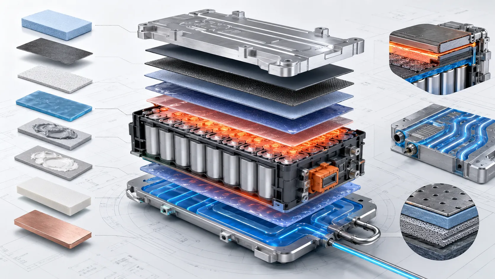
TIMs are categorized into distinct physical formats—ranging from highly conformable liquid-dispensable greases and gels to solid elastomeric pads and phase-changing compounds—each offering unique balances of thermal performance, mechanical compliance, and manufacturing ease.
Thermal Greases and Pastes
Greases are highly conformable, non-curing suspensions of thermally conductive fillers in a low-viscosity carrier oil. Under high clamping pressure, they can achieve ultra-thin BLTs below 20 µm, yielding excellent thermal impedance. Their primary advantage is the ability to wet even highly irregular surfaces without a pre-cure step. However, they lack structural integrity and are prone to pump-out effect during thermal cycling, as well as migration of the carrier fluid over time. Greases are best suited for applications with stable mechanical clamping and relatively uniform, rigid surfaces.
Thermal Gap Pads (Elastomeric Silicons and Non-Silicons)
Gap pads are pre-formed, compressible sheets that bridge large, variable gaps while providing electrical isolation. They simplify assembly because they require no dispensing or curing, and they can absorb mechanical tolerances and vibration. Their primary trade-off is a thicker minimum BLT, which increases thermal impedance. Silicone-based pads dominate for their softness and dielectric properties, but non-silicone or acrylic-based pads are used where outgassing (CVCM) or silicone oil bleed is a concern, such as in optical assemblies or cleanroom environments.
Phase Change Materials (PCMs)
Phase change materials (PCM) combine the handling convenience of a solid pad with the low thermal impedance of a grease. At room temperature they are solid films; at device operating temperatures they soften or melt, flowing into surface asperities to achieve a thin, void-free interface. This mechanism makes PCMs highly effective in applications with moderate clamping pressure and moderate surface roughness. They offer good reworkability and can partly resist pump-out because they re-solidify during cooling, but the phase change temperature must be matched to the application’s steady-state thermal range.
Dispensable Thermal Gels and Putties
Thermal gels are two-part or single-part silicone or non-silicone materials that cure in place, creating a compliant, stress-absorbing layer. They can be dispensed as a liquid to fill variable gaps, then cure to a soft solid that resists pump-out and migration far better than greases. Their gap-filling capability is similar to that of thick gap pads but without the need for die-cut parts. The trade-off is longer processing time (cure) and generally higher thermal impedance than a highly compressed grease. Gels are widely used in automotive electronics, battery modules, and telecommunication power amplifiers where robustness and automated dispensing are critical.
Metal-Based TIMs (Indium and Solder Alloys)
Metal TIMs, typically indium foils or solder-based preforms, achieve the highest bulk thermal conductivity (30–80 W/m·K) and can be reflowed into extremely thin bond lines with near-zero void content. They are reserved for high-flux applications such as high-power lasers or RF GaN devices, where the thermal demands exceed what organic-based materials can deliver. However, they require matching coefficients of thermal expansion (CTE) to avoid solder fatigue, offer no electrical isolation, and demand flux or fluxless reflow processes. Rework is often difficult and costly.
The table below provides a direct structural comparison of these formats across key design and manufacturing parameters.
| TIM Format | Bulk Thermal Conductivity Range (W/m·K) | Relative Bond Line Thickness (BLT) | Dielectric Strength (kV/mm) | Reworkability | Principal Failure/Degradation Mode |
|---|---|---|---|---|---|
| Thermal Grease | 0.5–6.0 | Very thin (≤25 µm) | N/A (non-isolating) | Moderate cleaning needed | Pump-out, dry-out, migration |
| Gap Pad (silicone) | 1.0–12.0 | Medium to thick (0.5–5.0 mm) | 8–20+ | Easy – peel and replace | Compression set, oil bleed |
| Phase Change Material | 1.5–8.0 | Thin (25–100 µm after reflow) | Up to 10+ | Good – re-melt and clean | Phase change cycling, potential dry-out |
| Thermal Gel / Putty | 1.0–10.0 | Variable (0.1–3.0 mm) | 10–25+ | Moderate – bonded but removable | Incomplete cure, void formation during dispense |
| Metal TIM (Indium / Solder) | 30–80+ | Ultra-thin (25–75 µm) | Conductive – not isolating | Difficult – requires reflow equipment | Solder fatigue, CTE mismatch, voiding |
Note: Ranges reflect typical commercial offerings. Specific properties depend on filler type, loading, base polymer, and cure chemistry; always request data sheets for the exact formulation under your intended operating conditions.
Mechanical, Environmental, and Reliability Standards
Long-term reliability of a TIM depends on its resistance to environmental stresses such as thermal cycling, which can cause fluid migration (pump-out) or loss of volatile carriers (dry-out). Electrical isolation and outgassing performance further constrain choices in high-reliability sectors.
Pump-Out, Dry-Out, and Rheological Stability
Thermal greases are the most susceptible to pump-out. As the joined surfaces expand and contract at different rates, a pumping action displaces the grease from the center toward the perimeter, causing a gradual increase in thermal impedance. Dry-out occurs when volatile fractions in the carrier fluid evaporate over time, leaving behind a dry, poorly conductive filler cake. Phase change materials and curable gels avoid pump-out because they form a stable, non-flowing layer at operating temperature. When evaluating a TIM for cyclical reliability, request thermal impedance data after thousands of powered temperature cycles, not just initial values.
Dielectric Strength and Electrical Isolation Properties
In many power modules and battery electronics, the TIM must serve as a primary or secondary electrical insulator between live electrodes and a grounded heat sink. Here, dielectric breakdown voltage becomes a critical parameter, typically measured in kV/mm. Gap pads and gels can be formulated with high dielectric strength (above 15 kV/mm) to withstand nominal voltages with safety margins. However, thickness directly influences isolation capability; a too-thin bond line may meet thermal targets but compromise insulation. Engineers must verify that the minimum as-assembled thickness under worst-case tolerance stacking still exceeds the required isolation voltage per applicable standards.
Outgassing in High-Vacuum and Aerospace Environments (ASTM E595)
In space and high-vacuum optics, any volatile organic compound that outgasses from a TIM can condense on cold surfaces—mirrors, lenses, sensors—degrading performance. The standard ASTM E595 test quantifies Total Mass Loss (TML) and Collected Volatile Condensable Materials (CVCM). Stringent applications often require TML < 1.0% and CVCM < 0.1%. Silicone-based TIMs can be particularly problematic, as low-molecular-weight siloxanes volatilize and redeposit. For these environments, specialized low-outgassing gap pads, non-silicone putties, or metal foils are typically specified.
Industrial Application Profiles and Thermal Design Scenarios
Industrial TIM selection is driven by the specific operating environment: EV battery modules require high dielectric strength and vibration dampening, whereas high-frequency telecommunications systems prioritize ultra-low thermal impedance and automated dispense compatibility.
Automotive Electronics and EV Powertrains
Automotive power electronics, from onboard chargers to traction inverters, see wide temperature swings, mechanical shock, and stringent lifetime requirements. In battery thermal management, TIMs must accommodate large cell-to-cooling-plate gaps while withstanding thousands of charge/discharge cycles. Cured thermal gels and thick gap pads are preferred for their resilience and high dielectric isolation. Additionally, many automotive OEMs mandate silicone-free materials inside paint-shop environments to avoid surface adhesion defects; this drives demand for silicone-free pads and thermal battery solutions that avoid volatile siloxanes.
Telecommunications Infrastructure and High-Power RF Modules
5G base station power amplifiers and optical transceivers generate concentrated heat loads but demand thermally stable performance over 10–15-year field lives with minimal maintenance. Phase change materials are frequently used because they provide a thin, grease-like interface without the pump-out risk, and they are amenable to automated placement. In remote radio heads where environmental sealing and gravity cycles matter, pre-cured gap pads or dispensable thermal interface materials products that cure to a soft solid ensure no material migration over time.
Power Semiconductors and IGBT Modules
Isolated Gate Bipolar Transistors (IGBTs) and MOSFETs in industrial drives often use ceramic substrates that are relatively flat but electrically live. The TIM must provide a thin bond line, high thermal conductivity, and sufficient dielectric isolation. High-performance greases applied under controlled, uniform clamping remain common, while newer gel-based approaches are gaining ground to eliminate pump-out issues. For the highest heat fluxes, metal solders are considered, but the CTE mismatch with the ceramic substrate must be carefully managed.
For applications demanding tailored thermal interface solutions for BMS thermal management or integrated custom battery pack design, we offer engineering consultation and sample provisioning.
Request a Technical Consultation and Custom TIM Samples
Optimizing thermal management requires balancing material properties with physical assembly parameters. Our engineering team can assist in selecting, modeling, and customizing TIM solutions to meet your specific design-in requirements. Whether you need die-cut PCM samples for a new EV inverter, a low-outgassing formulation for aerospace optics, or a non-silicone gel for automated dispensing, we provide application-specific support backed by Kingchi’s thermal solutions and extensive manufacturing capabilities.
From initial thermal simulation to pilot production, we help verify that the chosen TIM meets your impedance targets under real clamping conditions. Reach out to discuss your performance envelope, obtain specification data sheets, and arrange prototype samples of thermal interface materials products for your next qualification cycle.
Frequently Asked Questions
What is the difference between thermal conductivity and thermal impedance?
Thermal conductivity is a bulk material property (W/m·K) that describes intrinsic heat transfer through a homogeneous sample. Thermal impedance (e.g., °C·in²/W) is a system-level measurement that includes contact resistances and bond line thickness, directly reflecting how a TIM will perform in an actual assembly.
How does clamping pressure affect the performance of a thermal gap pad?
Increased pressure compresses the pad, reducing its bond line thickness and enlarging the effective contact area, which lowers total thermal impedance. Beyond a certain pressure, thickness reduction plateaus, and further loading may risk board warpage or component stress without significant thermal gain.
What causes the “pump-out” effect in thermal pastes, and how can it be prevented?
Pump-out occurs when thermal cycling causes joined surfaces to expand and contract at different rates, physically pumping the uncured grease out of the interface. Switching to a phase change material or a cured thermal gel eliminates this risk because the TIM becomes a stable solid layer at operating temperature.
Are silicone-free TIMs necessary?
Silicone-free TIMs are required when silicone oil bleed or volatile siloxanes can impair optical surfaces, coating adhesion in automotive paint lines, or high-vacuum aerospace equipment. They prevent contamination in sensitive environments and are available in gap pad, gel, and putty formats.
Frequently Asked Questions
Get a Fast, Custom Power Quote