Custom Battery Pack Design Guide: Specifying OEM Power Systems
When an engineering team sets out to specify a custom battery pack design, the most critical decision is rarely the enclosure shape. It’s the electrical architecture and cell chemistry that determine whether the pack will survive field conditions, meet certification deadlines, and stay within lifecycle cost targets. We see too many programs burn schedule and budget by optimizing for energy density on the spec sheet while overlooking thermal management and cell matching. This guide gives you the engineering and procurement framework we use at Kingchi to help OEM partners lock in the right topology, chemistry, and BMS strategy before the first prototype is built.
Defining Electrical Architectures: Voltage, Capacity, and Configuration
A custom battery pack’s configuration must balance voltage (achieved via series connections) and capacity (achieved via parallel groups). System designers should use the formulas Vtotal = Vcell × S and Ahtotal = Ahcell × P to establish baseline electrical thresholds before ever touching mechanical CAD.
Series vs. Parallel Cell Architectures
Series strings multiply the nominal voltage of a single cell to reach the required system bus voltage. If you need 24 V from a 3.6 V nominal cell, you require 7 cells in series. Parallel groups, on the other hand, stack capacity by combining cells whose positive and negative terminals are tied together. A 3S2P configuration is six cells total—three in series, two of those strings in parallel—useful when you need to increase both voltage and runtime. In custom battery pack design services, we always map the extreme voltage limits first. A fully charged lithium-ion cell can reach 4.2 V, so the pack’s upper voltage must not exceed the load’s absolute maximum rating. The same holds for the cutoff voltage, typically 2.5–3.0 V per cell, to prevent deep discharge damage.
Buyer warning: Mismatched cell internal resistances inside a parallel block cause uneven current sharing. The “barrel effect” emerges instantly: the weakest cell dictates the overall pack performance. That’s why cell balancing techniques and grade‑A cell screening are non‑negotiable for production packs.
Calculating Capacity, Voltage Swings, and Continuous System Draw
Beyond nominal ratings, you need to model the pack under the actual load profile. Use the continuous discharge current and the pack’s DC internal resistance to compute voltage droop under load: Vdroop = I × Rpack. For pulsed loads, transient voltage dips can trigger early low‑voltage cutoff even if the average SoC is healthy. We always ask OEM engineers to provide the peak current duration and minimum operating voltage. From there, you can define the required parallel cell count to keep voltage above the system’s brown‑out threshold during the worst‑case transient.
Decision rule: If a pack must deliver a 20 A continuous draw from 18650 cells rated 10 A each, you need at least 2P. But thermal derating and aging need headroom—3P is a safer production choice.
Battery Chemistry Selection: Matching Applications to Cell Chemistries
The choice of battery chemistry depends on the application’s priority: specify Lithium Nickel Manganese Cobalt Oxide (NMC) for space‑constrained applications requiring maximum energy density, or Lithium Iron Phosphate (LFP) for systems prioritizing long cycle life, high thermal stability, and lower cost per cycle.
Evaluating Lithium‑Ion NMC vs. LFP Chemistries
NMC cells offer higher nominal voltage (3.6–3.7 V) and energy density (150–220 Wh/kg), making them attractive for handheld medical devices and UAVs. LFP cells operate at a flatter voltage curve (3.2 V nominal) with energy density around 90–120 Wh/kg, but they routinely exceed 2,000 full‑depth‑of‑discharge cycles and have a thermal runaway onset temperature roughly 100 °C higher than NMC. For industrial AGV packs that charge multiple times per day, the LFP cycle‑life advantage often eliminates the weight and volume penalty.
| Parameter | NMC | LFP |
|---|---|---|
| Nominal voltage | 3.6–3.7 V | 3.2 V |
| Energy density | 150–220 Wh/kg | 90–120 Wh/kg |
| Cycle life (80% DoD) | 500–1,000 | 2,000–4,000 |
| Thermal runaway onset | ~200 °C | ~300 °C |
| Relative cost per kWh | Medium‑high | Lower |
Data based on commonly available cylindrical 18650/21700 cells. Verify specific cell datasheets; parameters vary by manufacturer and form factor.
When to Specify Alkaline, NiMH, or NiCd for Niche Industrial Needs
While lithium dominates new designs, legacy industrial tools, emergency lighting, and extreme‑temperature equipment still rely on older chemistries. NiCd can operate from −40 °C to +60 °C and tolerates overcharge abuse, making it a fit for aviation and rail safety systems. NiMH offers better energy density than NiCd but suffers from high self‑discharge. Alkaline primary cells still appear in low‑duty‑cycle remote sensors because of their 10‑year shelf life. We advise procurement teams to verify that these chemistries still meet current transport and disposal regulations, especially in Europe under the Battery Directive.
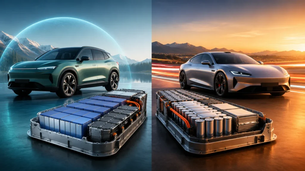
Mechanical Design and Physical Packing Geometry
Cylindrical cell topologies remain the standard for high‑vibration industrial applications due to superior structural integrity and heat dissipation, while prismatic cells are optimal for space efficiency in high‑capacity systems.
Form Factors: Cylindrical vs. Prismatic and Pouch Cells
Cylindrical cells (18650, 21700, 26650) have a steel can that resists swelling and mechanical abuse. They also create natural air gaps between cells, aiding passive cooling. Prismatic cells pack tightly and can yield higher volumetric energy density, but they require compression plates to prevent delamination. Pouch cells are the lightest but demand rigid enclosures to avoid punctures and gas buildup. In a custom battery pack manufacturer selection, we look for assembly lines that can handle the cell‑interconnect welding and fixture required for the chosen form factor.
Enclosure Materials, Packing Geometries, and Potting Decisions
Enclosure material selection directly impacts thermal path, weight, and ingress protection. Common options:
- ABS/PC blend: Economical, good for IP54 consumer electronics, limited heat conduction.
- Aluminum (6061‑T6): Excellent heat spreading, structural rigidity, natural EMI shielding; anodizing required for corrosion protection.
- Polycarbonate: High impact strength; used where transparency or UL94 V‑0 flame rating is needed.
Packing geometry impacts both cooling and vibration survival. Ladder layouts (single‑row cylinders) maximize surface area for passive cooling. Face‑centered cubic (FCC) packing increases cell count in a given volume but restricts airflow. For high‑vibration environments, we often specify thermally conductive potting compounds that lock cells in place while improving heat transfer to the enclosure wall—simultaneously raising the effective IP rating.
Engineering takeaway: The resistance of nickel strip interconnects becomes critical above 5 A continuous. For high‑current designs, pure nickel strips must be sized for I²R losses, and physical placement of thermistors should be adjacent to the highest‑current junctions to catch localized heating early.
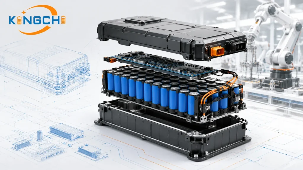
Battery Management System (BMS) Architecture & Thermal Engineering
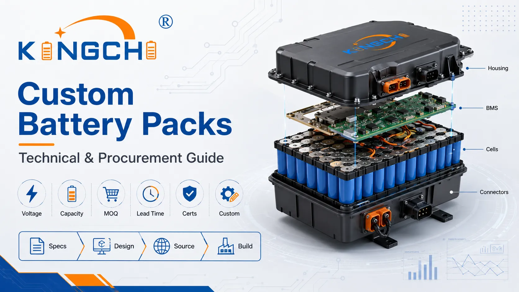
Every custom battery pack design requires a Battery Management System (BMS) to act as the primary safety layer, continuously monitoring cell voltage, current, and temperature to keep the pack within its Safe Operating Area (SOA). Without a properly tuned BMS, even the best cells degrade rapidly or become dangerous.
BMS Protection Schemes and Smart Battery Communication Protocol
A production‑grade BMS enforces four hard limits: over‑charge voltage cutoff, over‑discharge voltage cutoff, over‑current (both short‑circuit and sustained), and temperature out‑of‑range. Beyond basic protection, BMS integration in custom packs increasingly includes SMBus or I²C communication, enabling the host system to read State of Charge (SoC), pack temperature, and cycle count in real time. For medical and military systems, we implement redundant protection—a secondary protector IC in series with the primary—to meet single‑fault tolerance requirements.
Active vs. Passive Thermal Management and Runaway Mitigation
Passive strategies—such as phase‑change materials (PCMs) that absorb heat during a high‑rate discharge—work well for packs with intermittent duty cycles. Active cooling, whether forced‑air or liquid‑cooled cold plates, becomes necessary when the pack’s sustained heat generation exceeds the enclosure’s natural dissipation capacity. In addition to thermal control, every high‑reliability pack must incorporate thermal runaway mitigation features:
- Inter‑cell fire barriers (mica sheets or ceramic fiber separators) to arrest propagation.
- Venting paths that channel gases away from adjacent cells and personnel.
- Enclosure materials rated to contain a single‑cell thermal event without breaching.
What to verify: Ask your BMS supplier for the protection response time and whether the MOSFET gate drivers are designed to break the full short‑circuit current without latching. A slow OCP response turns a parallel pack into an arc welder.
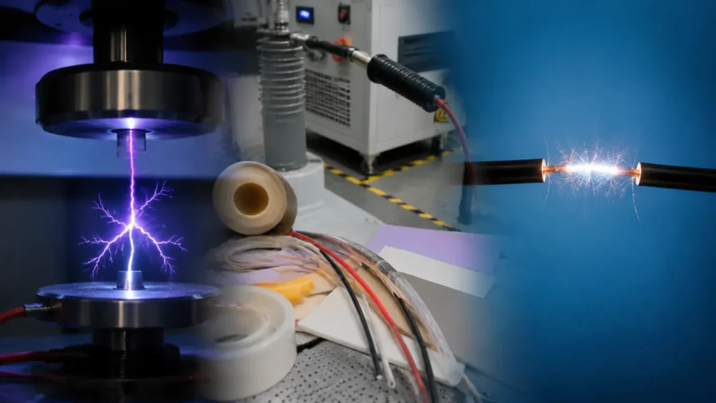
Regulatory Compliance, Testing, and Safety Certifications
Sourcing teams must design with compliance in mind; no custom lithium battery pack can legally ship globally without passing UN38.3 transport safety testing, which requires rigorous thermal, vibration, and mechanical testing.
Critical Global Standards: UN38.3, UL, and IEC
The regulatory landscape can dictate your cell choice and pack architecture. Below is a condensed map of the standards OEM buyers encounter most often:
| Standard | Scope | Key Tests |
|---|---|---|
| UN38.3 | Transport safety for lithium cells/batteries | Altitude simulation, thermal cycling, vibration, shock, external short circuit, impact/crush, overcharge, forced discharge |
| UL 2054 | Household and commercial battery packs | Abnormal charging, forced discharge, limited power source test, temperature‑dependent leakage current |
| IEC 62133 | Portable sealed secondary cells/batteries | Continuous low‑rate charging, vibration, moulded case stress, high‑rate charging |
| ECE R100 | Electric vehicle traction packs | Vibration, thermal shock, fire resistance, overcharge, over‑discharge, short circuit |
This is a simplified summary. Always confirm the exact edition and any national deviations with the testing laboratory before locking the design.
The New Product Introduction (NPI) and Testing Protocol
We structure our New Product Introduction (NPI) process around three gate reviews. First, a design review confirms that the cell, BMS, and enclosure meet the performance specification. Second, a pre‑compliance test phase subjects engineering prototypes to abbreviated environmental chamber stress cycles and drop tests to uncover weak points early. Third, formal certification testing at an ISO/IEC 17025 accredited lab validates UN38.3 and any applicable UL/IEC standards. Skipping pre‑compliance is the fastest way to blow your launch schedule. UN38.3 certification testing alone can take 4–6 weeks if everything passes on the first attempt; a single failure can add months.
Buyer warning: Always verify whether your pack assembler performs the critical test sequences in‑house or outsources them entirely. Integrated testing capability—even for early screening—reduces iteration lag and communication gaps.
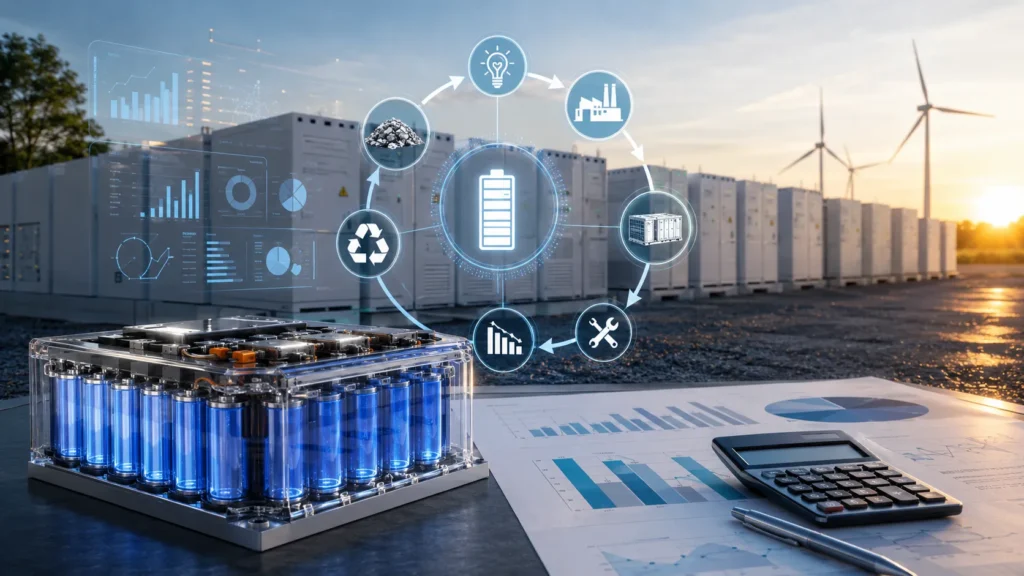
Sourcing Economics: Total Cost of Ownership (TCO) and Sourcing Strategies
A robust custom battery pack sourcing strategy must look beyond initial piece‑part costs to evaluate the total lifecycle cost, including shipping tariffs, certification lead times, and the risk of counterfeit or sub‑grade cells.
Onshore vs. Offshore Custom Battery Pack Manufacturing
Offshore assembly in China or Southeast Asia can lower the bill of materials by 15–25% due to cell pricing and labor rates. However, that advantage shrinks when you factor in air freight for prototypes, iterative engineering travel, and the 8‑12% tariffs on lithium‑ion packs imported into the US. Onshore partners often provide faster design‑for‑manufacturability (DFM) feedback and stronger IP protection. For medical or defense programs where ITAR or EAR compliance prohibits foreign access to technical data, onshore sourcing is mandatory. For commercial products, a hybrid model—offshore mass production paired with onshore NPI and first‑article inspection—frequently optimizes both cost and speed. Check out battery pack design solutions that can bridge both models.
Supply Chain Risks, Cell Integrity, and Lifecycle Cost Management
Cell counterfeiting remains the single largest hidden cost driver in custom battery pack procurement. Low‑cost cells marketed as “Grade A” often are factory seconds, salvaged, or relabeled used cells. We require full lot‑traceability documentation from cell manufacturers and perform sample discharge testing before accepting any batch. Lifecycle cost management also accounts for field maintenance. A pack designed with replaceable cell blocks can extend system life by 3–5 years versus a fully potted design that requires complete replacement at end of life.
Risk if ignored: Sourcing a pack solely on upfront price, without auditing cell provenance and manufacturing quality systems (ISO 9001, and ISO 13485/AS9100 where required), will result in premature field failures, warranty claims, and eventually a UL/UN38.3 suspension if the cells prove non‑compliant.
The Custom Battery Pack Design & Procurement Decision Matrix
Sourcing managers should utilize a structured risk‑evaluation framework before releasing design specifications, grading key parameters like safety profiles, lead times, and physical constraints. We use a two‑part approach: an engineering specification checklist and a supplier risk matrix.
B2B Engineering Specification Checklist
Before sending an RFQ, the OEM team must lock down these parameters—otherwise the quotes you receive will be incomparable:
- Operational voltage range (minimum, nominal, maximum).
- Continuous discharge current and peak current (with duration).
- Space envelope dimensions and mounting constraints (including connector protrusions).
- Operating temperature range (charge and discharge).
- Required cycle life or calendar life target.
- Target certification standards (UN38.3, UL 2054, IEC 62133, MIL‑STD‑810 if military).
- Communication protocol (SMBus, CAN, I²C, or none).
- Ingress protection rating (IP54, IP65, IP67).
Architecture and Sourcing Risk Evaluation Matrix
The following matrix helps weigh design choices against procurement risks. Assign a priority score (1‑5) for each row based on your program’s constraints, then map candidate suppliers against these categories.
| Factor | Design Choice | Procurement Risk | Mitigation |
|---|---|---|---|
| Chemistry | NMC (high density) vs. LFP (safety) | NMC: stricter certification testing LFP: weight penalty | Run pre‑compliance UN38.3 on candidate cells |
| Form factor | Cylindrical vs. prismatic | Cylindrical: more weld joints Prismatic: compression‑plate sourcing | Audit cell interconnect welding process |
| BMS topology | Single‑chip vs. discrete redundant | Single‑chip: no fault tolerance Redundant: higher BOM cost | Specify according to system safety level |
| Enclosure | Aluminum vs. ABS | Aluminum: higher machining cost ABS: poor thermal path | Thermal simulation before tooling |
| Supplier location | Onshore vs. offshore | Offshore: IP protection, tariffs Onshore: piece‑price premium | NDA, source‑code escrow, hybrid model |
Decision rule: If safety certifications or cycle life dominate your requirements, start with an LFP‑based design and select a supplier that can provide full cell lot‑traceability and in‑house BMS firmware development. For volume‑constrained consumer devices, NMC is often the only chemistry that fits, but it demands more rigorous thermal validation and a conservative BMS design.
For deeper guidance, refer to our custom battery pack products to see how these trade‑offs manifest in real-world pack configurations.
Partnering on Your Custom Battery Pack Project
Developing a reliable custom battery pack requires early and continuous collaboration between system engineers and the pack manufacturer’s design team. The most efficient NPI cycles happen when the buyer comes to the first meeting with a complete operational brief. To start a project with Kingchi, you’ll need:
- Operational voltage range and load profile (steady‑state and peak).
- Physical space envelope and mounting interface drawings (STEP or DXF).
- Target operating temperature range and ambient conditions.
- Required certifications (UN38.3, UL, IEC, MIL‑STD‑810, etc.).
- Desired form factor and enclosure material preference, if known.
- Communication protocol and any digital data (SoC, SoH) that must be reported.
From there, our team performs a feasibility analysis, cell screening, and a preliminary thermal simulation—typically within two weeks. This upfront engineering avoids costly redesign loops later. If you’re ready to move forward, our custom battery solutions page outlines our standard engagement models, from NPI‑only to turnkey production.
What to verify: Always ask a prospective partner for a sample DFM report from a past program that shares mechanical or electrical similarities with yours. It reveals how they think about manufacturability and design constraint trade‑offs.
Frequently Asked Questions
What is the typical timeline for custom battery pack design and certification?
Initial design and cell selection usually take 2–4 weeks, prototyping spans 4–8 weeks depending on tooling complexity, and full compliance certification (UN38.3, UL, IEC) can add 8–16 weeks, heavily influenced by testing lab queue times and whether any failures require redesign.
Why is cell matching critical in series‑parallel configurations?
Mismatched internal resistance or capacity forces weaker cells to reach end‑of‑discharge voltage first, dragging down the entire parallel group’s usable capacity and causing accelerated degradation and potential overheating during charge.
How does a Battery Management System (BMS) extend the pack’s operational lifespan?
By continuously balancing cell voltages and keeping every cell within its safe voltage and temperature window, the BMS prevents over‑charge and over‑discharge events that would otherwise degrade individual cells and shorten the overall pack lifespan.
What are the primary thermal management strategies for high‑draw custom battery packs?
Mid‑range packs often use passive strategies like thermally conductive potting and inter‑cell air gaps, while high‑draw packs, especially those with continuous discharge above 3C, typically require active forced‑air cooling or liquid cold plates to keep cell temperatures below critical thresholds.
How does the choice of nickel strip resistance impact overall pack efficiency?
Higher‑resistance nickel strips generate I²R power losses that manifest as localized heat, reducing usable energy, raising cell temperature, and stressing nearby cells—especially in high‑current designs where undersized interconnects can become the primary thermal bottleneck in the custom battery pack design.
Frequently Asked Questions
Get a Fast, Custom Power Quote